
Silicon carbide semiconductor device and method for manufacturing the same

a silicon carbide and semiconductor technology, applied in the field of semiconductor devices, can solve the problems of increasing current loss and high resistance, and achieve the effects of low resistance, excellent device characteristics, and large mobility of carriers

Active Publication Date: 2010-09-09
TOYOTA JIDOSHA KK +1
View PDF14 Cites 13 Cited by
  • Summary
  • Abstract
  • Description
  • Claims
  • Application Information

AI Technical Summary

Benefits of technology

[0017]The present invention provides a silicon carbide semiconductor device having a large mobility of carriers in the channel forming region, a low on resistance, and excellent in the device characteristics, as well as a manufacturing method thereof.

Problems solved by technology

However, in the silicon carbide (SiC), since the mobility of carriers is generally small, the MOS interfacial characteristic is insufficient, and the channel mobility of the MOS transistor is small, there has been a problem that on resistance is high and current loss increases when it is formed as a device.

Method used


Image

  • Silicon carbide semiconductor device and method for manufacturing the same
  • Silicon carbide semiconductor device and method for manufacturing the same
  • Silicon carbide semiconductor device and method for manufacturing the same

Examples


first embodiment

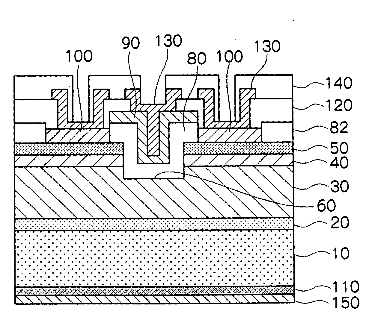
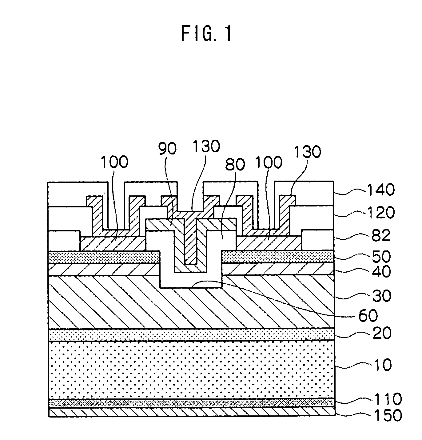
[0033]FIG. 1 is a cross sectional view showing a silicon carbide semiconductor device of the invention. The silicon carbide semiconductor device of this embodiment is constructed as vertical MOS type field effect transistor (MOSFET) in which a gate electrode is constituted as a MOS structure and carriers move in the vertical direction for vertically traversing the inside of the device between the source electrode disposed on one surface of a silicon carbide substrate and a drain electrode disposed on the side opposite to the source electrode forming surface.

[0034]In MOSFET of this embodiment, an SiC buffer layer 20 (N+; N2-doped, carrier concentration: 3×1018 cm−3) of 1 μm thickness, an SiC drift layer 30 (N−N2-doped, carrier concentration: 5×1015 cm−3) of 10 μm thickness, a channel layer 40 of 2 μm thickness including Ge granular crystals (P−; Al-doped, carrier concentration: 5×1015 cm−3) disposed on the SiC drift layer 30 and having 0.5 μm height in the direction of the thickness ...

second embodiment

[0074]FIG. 14 is a cross sectional view showing the silicon carbide semiconductor device according to the invention. The silicon carbide semiconductor device of this embodiment is constructed as a lateral MOS field effect transistor (MOSFET) in which a gate electrode is constituted as a MOS structure and carriers move between the source electrode and the drain electrode disposed on one surface of the silicon carbide substrate in the direction of the plane of the silicon carbide substrate in the device.

[0075]In the MOSFET of this embodiment, an SiC buffer layer 220 (P; Al-doped, carrier concentration: 1×1016 cm−3) of 1 μm thickness, an SiC field layer 230 (P; Al-doped, carrier concentration: 1×1017 cm−3) of 3 μm thickness, a channel layer 240 of 2.0 to 2.2 μm thickness including Ge granular crystals (P−; Al-doped, carrier concentration: 1×1017 cm−3) disposed on the SiC field layer 230 having 0.2 μm height in the direction of the thickness of an SiC substrate 210 and a cap layer (P−; ...


PUM


Abstract

A channel layer (40) for forming a portion of a carrier path between a source electrode (100) and a drain electrode (110) is formed on a drift layer (30). The channel layer (40) includes Ge granular crystals formed on the drift layer (30), and a cap layer covering the Ge granular crystals.

Description

TECHNICAL FIELD[0001]The present invention relates to a semiconductor device using silicon carbide (SiC) and a method for manufacturing the same.BACKGROUND ART[0002]In recent years, a field effect transistor (FET) having a gate electrode disposed between a source electrode into which a current flows and a drain electrode from which it flows out for controlling the current (drain current) between source / drain by a voltage applied to the gate electrode has been proposed. The field effect transistor includes an MOS type (MOSFET) having a MOS structure fir the gate and a junction type using a pn junction or a Schottky junction.[0003]In MOSFET having the MOS structure for the gate electrode, the conductivity of a channel region through which the drain current flows is controlled by utilizing that an inversion layer due to minor carriers is formed on the surface of a semiconductor. Then, since the current value changes when a gate voltage is changed, it can function for amplification of e...

Claims


Application Information

Patent Timeline
Patent Type & Authority Applications(United States)
IPC IPC(8): H01L29/24H01L21/20
CPCH01L21/02378H01L29/165H01L21/0245H01L21/02529H01L21/02532H01L21/02573H01L21/0262H01L29/04H01L29/1608H01L29/161H01L29/4236H01L29/66068H01L29/78H01L29/7813H01L21/02447
Inventor SEKI, AKINORITANI, YUKARISHIBATA, NORIYOSHI
Owner TOYOTA JIDOSHA KK
Learn More