Method for producing optical member and optical member formed by the production process

a production method and technology of optical components, applied in the field of producing optical components and optical components by the production method, can solve the problems of difficult to obtain stable optical performance, difficult to achieve the full effect of introducing inorganic fine particles, serious deterioration of fluidity of resins, etc., to achieve high accuracy, facilitate shape control of optical components, and increase design freedom

Inactive Publication Date: 2010-09-09
FUJIFILM CORP
View PDF0 Cites 19 Cited by
  • Summary
  • Abstract
  • Description
  • Claims
  • Application Information

AI Technical Summary

Benefits of technology

[0026]According to a method for producing an optical member in an aspect of the invention, there can be formed an optical member of a desired shape by heat-compressing a nanocomposite material (i.e., polymer containing inorganic fine particles) taken out from a solution in a state of 15 mm−1 or more in specific surface area, and hence a high-quality, highly accurate optical member can be formed without taking a long period of time for removing the solvent. Also, the process facilitates shape control of the optical member, thus designing freedom being increased. In addition, the process can contribute to downsizing of an optical unit and enhancement of image resolution.

Problems solved by technology

However, of the above-described methods for producing nanocomposite materials, in the method (1) an uneven distribution of inorganic fine particle size is liable to occur and that stable optical performance is difficultly obtained.
Also, an increase in the concentration of inorganic fine particles serves to enhance the effect of dispersing the inorganic fine particles, but it causes serious deterioration of fluidity of the resin, thus it becomes difficult to obtain the full effect of introducing the inorganic fine particles.
This deterioration of fluidity starts to be caused when the addition amount of the inorganic fine particles is about 2% by weight, and the fluidity is clearly deteriorated when the addition amount is about 5% by weight.
With the method (2), polymerization of the monomer is accompanied by such a large contraction of volume that control of the resulting shape is difficult.
Thus, it becomes difficult to secure accuracy required by a highly accurate optical part such as an image-forming lens.
With the method (3), it is possible to produce a lens having the highest quality but, in the actual production steps for producing an optical member, removal of the solvent takes a long time.

Method used


Image

  • Method for producing optical member and optical member formed by the production process
  • Method for producing optical member and optical member formed by the production process
  • Method for producing optical member and optical member formed by the production process

Examples


first embodiment

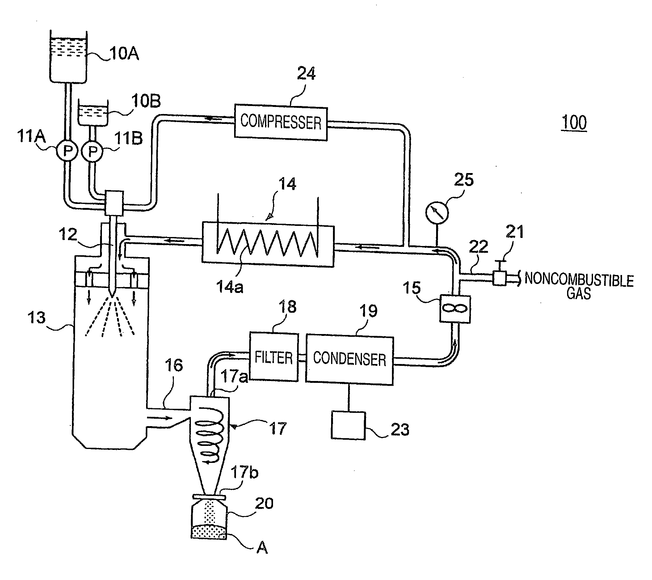
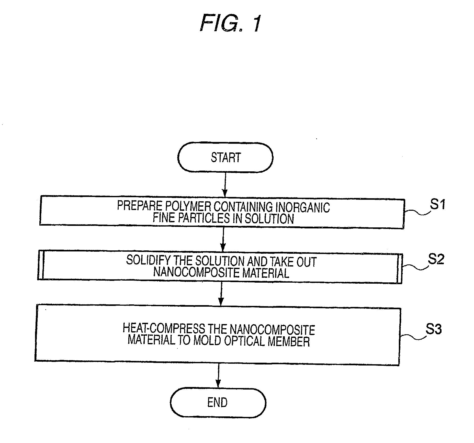
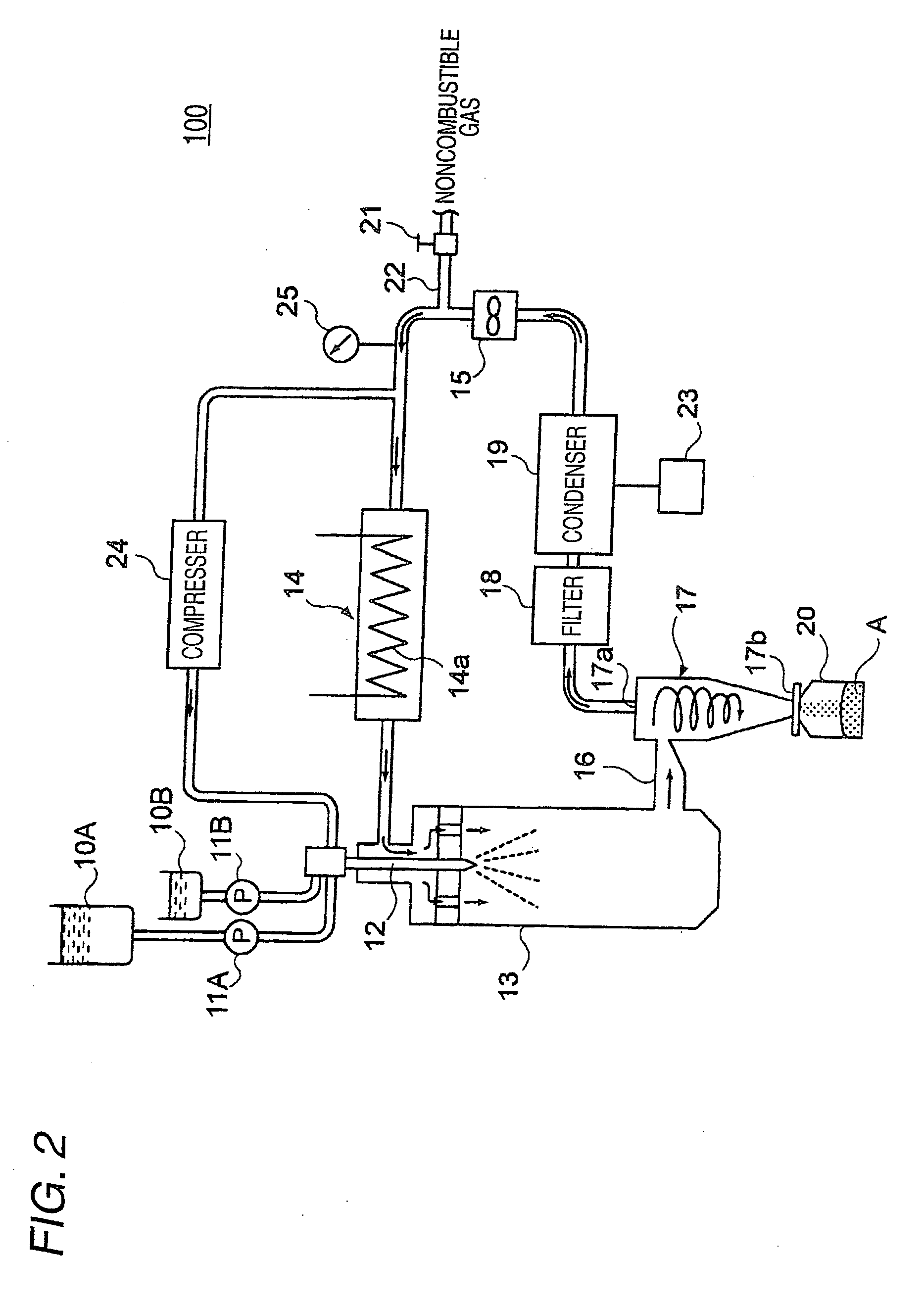
[0049]In the first embodiment, in order to conduct drying of the solution in the step S2 shown in FIG. 2, it is assumed to utilize a spray drying apparatus 100 of the constitution shown in FIG. 2 as one example. In the case of utilizing this spray drying apparatus, the solution is introduced into a high-temperature gas as finely atomized droplets to dry. In short, the solution is dried as droplets having an increased surface area, and hence the time required for drying it can be markedly shortened. However, the drying degree of the powdery nanocomposite material obtained by the spray drying apparatus treatment is not necessarily sufficient, and further drying is conducted by using a vacuum drying apparatus (see FIG. 4 to be described hereinafter).

[0050]The spray drying apparatus 100 shown in FIG. 2 is equipped with a solution tank 10A for storing a solution containing a nanocomposite material; a solution-feeding pump 11A; a solution tank 10B; a solvent-feeding pump 11B; a spray nozz...

second embodiment

[0100]Next, a second embodiment of the process of the invention for producing an optical member will be illustrated below.

[0101]In this embodiment, drying of the solution in the step S2 shown in FIG. 1 is conducted by employing a freeze-drying method in place of the method of forming a powdery nanocomposite material from the droplets of the solution. This freeze-drying method is a method of obtaining a massive nanocomposite material by vacuum-drying the solution to form a solid product and taking out it.

[0102]Generally, in employing the freeze-drying method, the solution is dried without forming droplets, and hence the time required for drying becomes comparatively long in comparison with the spray drying method and the inkjet drying method due to the difference of surface area in a wet form. However, at the point of completion of this freeze-drying, the freeze-dried product is in a state of being dried to about the same level as with the dry nanocomposite material B obtained by fur...

modified example 1

[0115]In the above-described embodiment, it is assumed that the nanocomposite material taken out of the tray 74 after freeze-drying is pulverized to form a nanocomposite material which is used to mold an optical member. However, it is also possible to mold an optical member without pulverizing.

[0116]For example, as is shown in FIG. 11, in expectation of the final shape of a lens, a groove 74Ba having a shape approximate to the final shape after compression under pressure is formed in the surface of the tray 74B disposed within the freeze-drying apparatus, and the solution is poured into this groove 74B to conduct freeze-drying. Thus, a nanocomposite material 79B taken out of the tray 74B after freeze-drying is obtained as a preform having a larger thickness than that of the final shaped lens. This preform is heated and compression-molded in a mold which receives one preform to thereby obtain a final shape lens. This method permits metering in a solution state and not in a powder sta...


PUM

PropertyMeasurementUnit
diameteraaaaaaaaaa
particle sizeaaaaaaaaaa
boiling pointaaaaaaaaaa

Abstract

A method for producing an optical member from a nanocomposite material which includes a thermoplastic resin containing inorganic fine particles is provided. The method includes:
    • a first step of preparing in a solution the thermoplastic resin containing the inorganic fine particles;
    • a second step of drying and solidifying the solution containing the prepared thermoplastic resin to produce the nanocomposite material having a specific surface area (surface area/volume) of 15 mm−1 or more; and
    • a third step of heat-compressing the produced nanocomposite material to form the optical member in a desired shape.

Description

TECHNICAL FIELD[0001]The present invention relates to a method for producing an optical material and to an optical member formed by the production method and, more particularly, to a technique of forming an optical material by using a nanocomposite material.BACKGROUND ART[0002]In recent years, with the performance enhancement, size reduction, and reduction in production cost of optical devices such as mobile cameras and optical information-recording devices such as a DVD drive, a CD drive, and an MO drive, excellent materials and excellent production steps have strongly been desired with respect to optical members such as optical lenses and filters to be used for these devices.[0003]In particular, plastic lenses are rapidly coming into wide use not only as lenses for spectacles but also as optical lenses because they are more lightweight and less breakable than lenses made of an inorganic material such as glass, because they can be processed into various shapes, and because they can...

Claims


Application Information

Patent Timeline
Patent Type & Authority Applications(United States)
IPC IPC(8): B29D11/00
CPCB29C43/021B29C2043/3618B29C2043/503C08J5/005B29L2011/0016B82Y30/00B29D11/00
Inventor EIHA, NORIKOWATANABE, SEIICHIYOSHIOKA, MASATO
Owner FUJIFILM CORP
Why Eureka
Try Eureka