
Optical assembly and method

a technology of optical assembly and assembly method, which is applied in the direction of surface/boundary effect, instruments, and drawing sample devices, etc., can solve the problems of reducing the path length of the conduit, so as to achieve the effect of constant light path length

Active Publication Date: 2010-09-09
PARAYTEC
View PDF5 Cites 17 Cited by
  • Summary
  • Abstract
  • Description
  • Claims
  • Application Information

AI Technical Summary

Benefits of technology

[0016]Advantageously, the present invention allows active dissolution of a sample of a substance, for instance a drug product, into a fluid stream to be imaged at a micron scale. This can provide information on the dynamic concentration of the drug product close to the surface of the dissolving sample. The Intrinsic Dissolution Rate (IDR) can thus be calculated. The array detector can be a 2D active pixel area imaging array. This allows quantitative measurement of dissolution of an active ingredient from the surface of a pharmaceutical formulation, which is not achievable by any previously known technique. The detector, such as is described in U.S. Pat. No. 7,262,847, is chosen to provide over 3 orders of magnitude of linear dynamic range which assists in picking out wide difference in substance concentration to enable accurate profiling. Furthermore, the high spatial resolution of the detector can given sharp imaging down to 7 μm in a direction transverse to the surface to maximise information quality. Direct monitoring of the concentration profile of the active pharmaceutical ingredient near the surface can be performed, which is a key parameter for studying dissolution.
[0050]The chamber may be quadrilateral-shaped in cross-section and in particular may be rectangular or square. This may provide advantages in terms of providing a constant light path length throughout the chamber. Alternatively, the chamber may be generally circular, elliptical, oval or other suitable shape in cross-sections. Portions of the chamber may have different shapes in cross-section.

Problems solved by technology

However, fluid flowing along a conduit such as a capillary is subject to friction and thus shear both between walls of the conduit and the fluid, and indeed between layers within the fluid itself.
However, the ratio of the diameter of the cell relative to that of the capillary is relatively small, dictated by factors including manufacturing constraints, and thus only provides a relatively small increase in the path length.
However, these techniques are not easily applied, for example, to quantitative investigation of the dissolution of a material into a fluid stream at source.
In particular, the apparatus disclosed in U.S. Pat. No. 5,061,361 cannot be applied to quantitative investigation of the dissolution of a material into a fluid stream at source.
One of the major challenges for formulation scientists when designing a tablet is ensuring that the active ingredient is released at the desired rate.
While product consistency can be measured, this provides little detailed information about the method of dissolution.
Drug product dissolution is complex and involves several fundamental processes such as hydration, disintegration, erosion and particle de-agglomeration, as well as dissolution of the drug substance itself.
However, this technique cannot be applied to image the active dissolution of the sample into a fluid stream.
Furthermore, most active ingredients in pharmaceuticals absorb in the UV spectrum rather than the visible region and so optical imaging using visible light is frequently ineffective.
However, the techniques described in all four papers assess the concentration downstream of the point of dissolution and therefore are ineffective for observing and measuring the process of drug product dissolution itself.
Again, however, there is no suggestion of observing and measuring the process of dissolution itself.
Furthermore, the described techniques require large media volumes, for instance of the order of 500-1000 ml, which is disadvantageous.
Hence, this technique and the techniques described in the above papers are deficient as they are obliged to make assumptions regarding the concentration profile and fail to provide a technique of measuring this key parameter directly.
Similarly, the “CE 7smart” system commercially available from Sotax AG of Switzerland provides a conventional flow through dissolution system which requires a large media volume and fails to allow for measurement at or near the surface of the sample.

Method used


Image

  • Optical assembly and method
  • Optical assembly and method
  • Optical assembly and method

Examples


Embodiment Construction

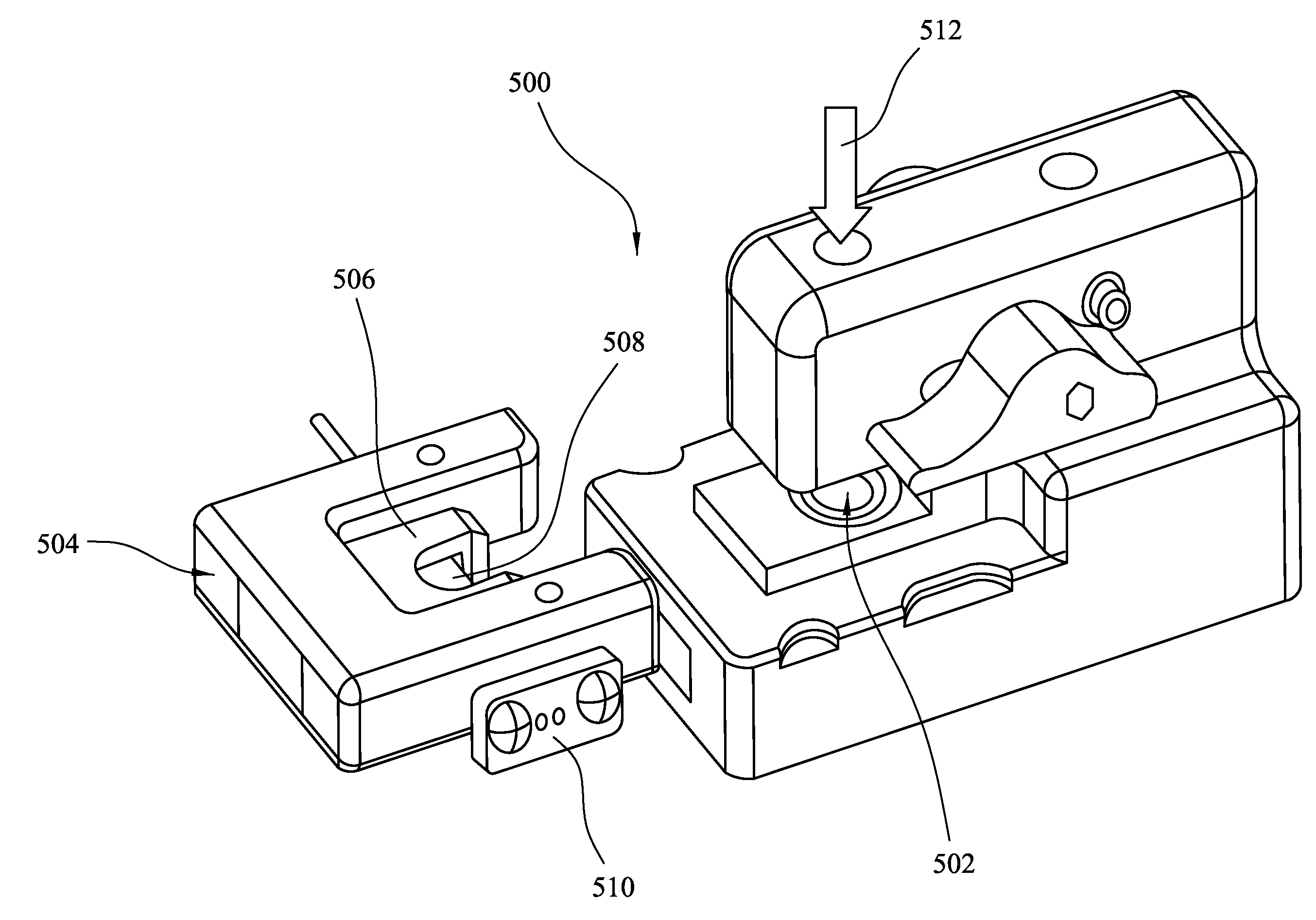
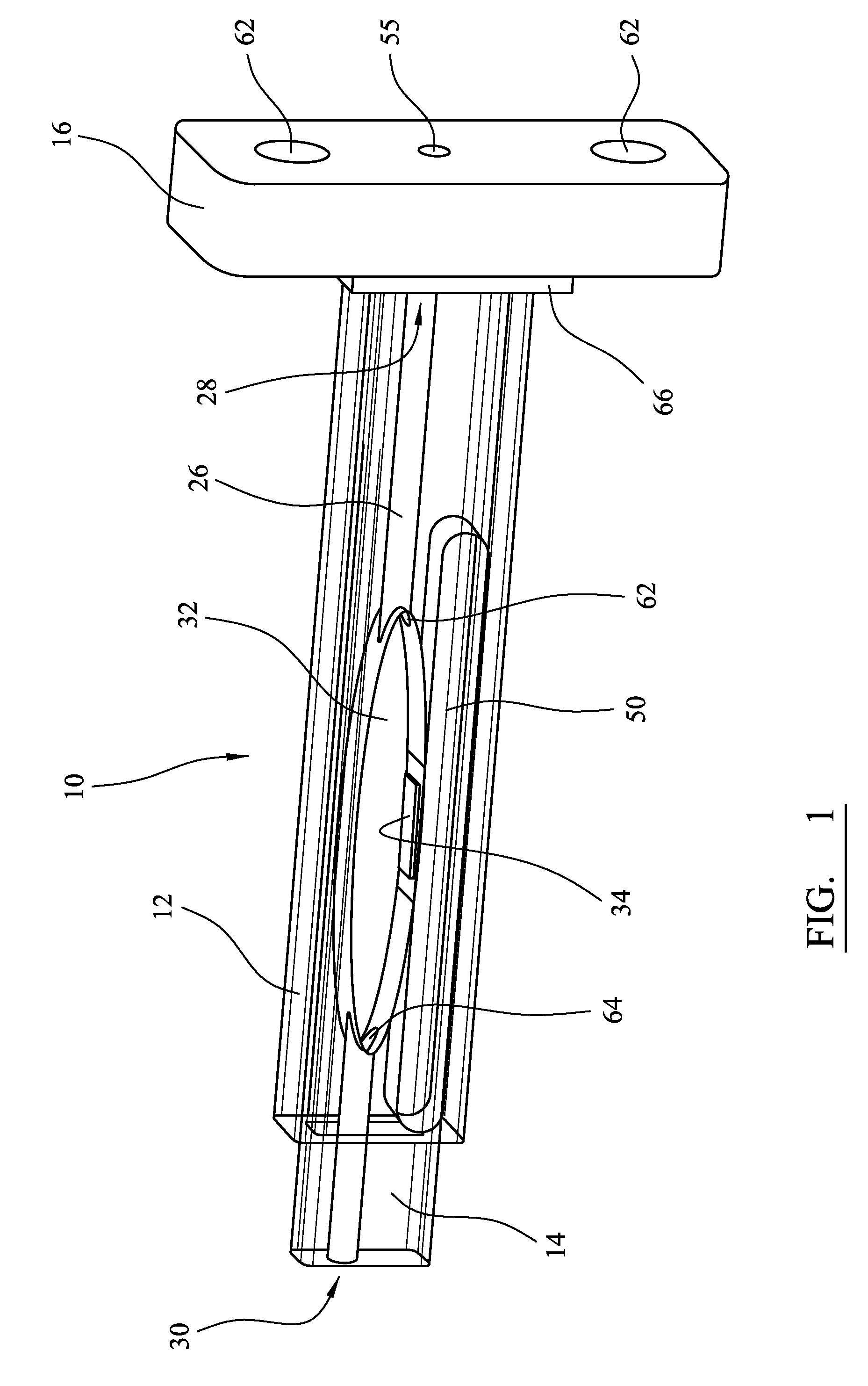
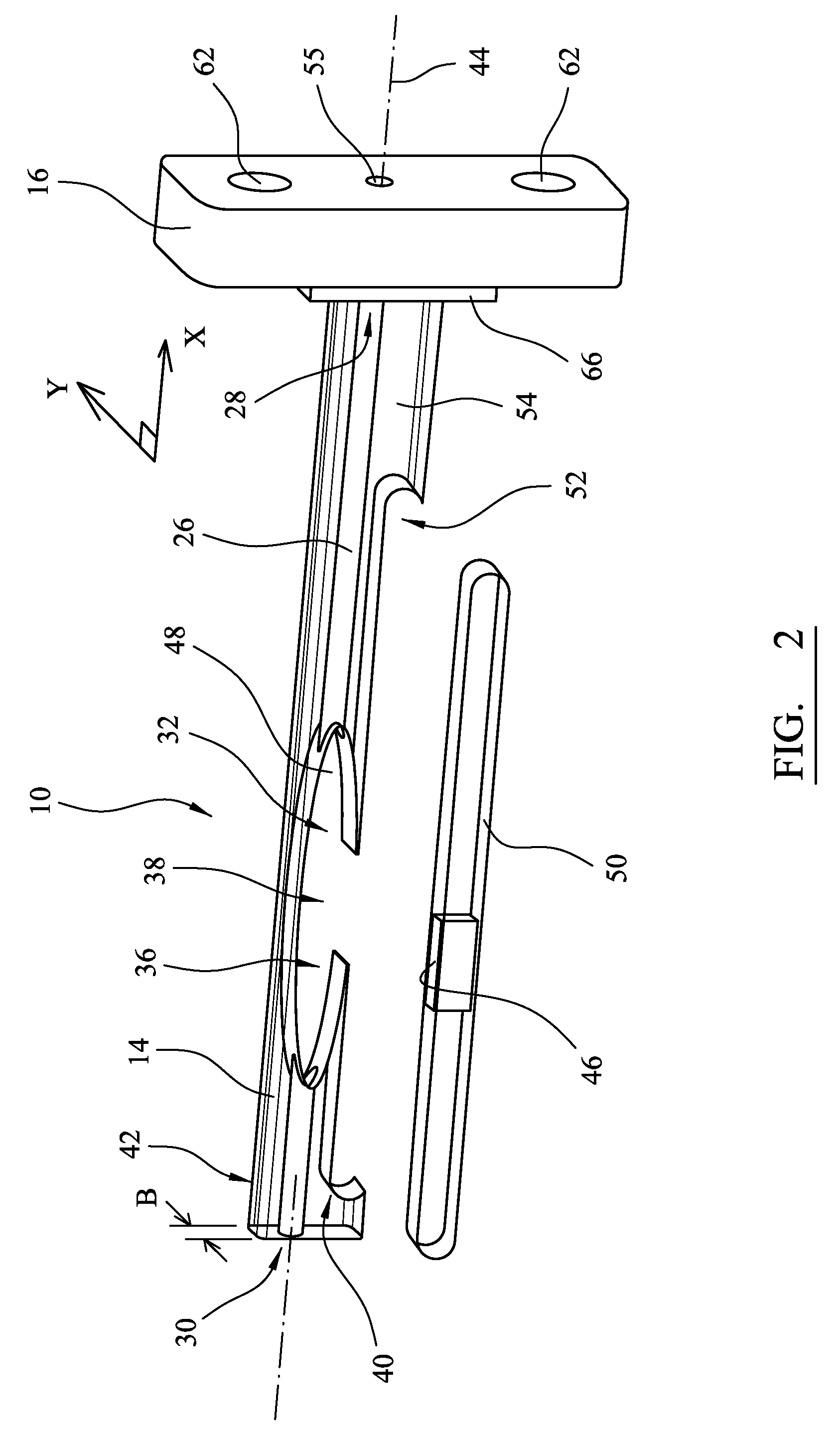
[0068]FIGS. 1 to 8 illustrate optical cell assemblies and cartridges arranged to receive samples of materials to be tested, and are described first. The dissolution of the samples into a fluid flow is to be tested. FIG. 9 illustrates an optical assembly, including an optical cell assembly and a cartridge, for imaging the dissolution of the sample into the fluid flow.

[0069]Turning firstly to FIG. 1, there is shown a perspective view of part of an optical cell assembly for use in testing a sample of material in accordance with an embodiment of the present invention, the optical cell assembly indicated generally by reference numeral 10. The assembly 10 generally comprises a hollow outer cell portion 12 and an insert portion 14 which is shaped to fit within the outer cell portion 12. In FIG. 1, part of the outer cell portion 12 has been removed to illustrate the relationship between the outer cell portion and the insert portion 14. Additionally and as will be described in more detail be...


PUM


Abstract

An optical apparatus and method comprising a light source, an array detector for area imaging and an optical cell assembly. The optical cell assembly comprises a chamber which is arranged to receive a sample of a material including an analyte, a fluid inlet and a fluid outlet coupled to the chamber. A fluid dissolution medium stream passes through the chamber such that the sample can dissolve into the dissolution medium. The chamber is in at least one light path created between the light source and the array detector. The array detector comprises a two dimensional array of detector locations arranged to provide an output signal indicative of the light absorbance of the analyte within the chamber such that the output of the array detector is indicative of the concentration profile of the analyte near the surface of the sample.

Description

[0001]The application claims priority under 35 U.S.C. 119 to U.K. Patent Application No. GB0903992.6, entitled “Optical Assembly and Method,” inventors James Hershell Lenke et al., filed Mar. 9, 2009, which application is herein incorporated by reference.FIELD OF THE INVENTION[0002]The present invention relates to an optical assembly and method for imaging dissolution. An optical cell assembly for use in testing a sample of a material is disclosed together with a cartridge comprising such an optical cell assembly and an apparatus for testing a sample of a material, the apparatus incorporating the optical cell assembly. In particular, but not exclusively, the present invention relates to an optical apparatus for use in testing a sample of a material to image dissolution of the material into a fluid stream in which light from a light source is passed through a sample to be tested where the sample is dissolving into a fluid stream, the light passing in a direction transverse to a main ...

Claims


Application Information

Patent Timeline
IPC IPC(8): G01N21/01G01N21/59
CPCG01N13/00G01N21/05G01N21/33G01N2021/0346G01N2021/0307G01N2021/0375G01N2013/006B33Y80/00
Inventor LENKE, JAMES HERSHELLMOON, KEVIN JAMESGOODALL, DAVID MURRAY
Owner PARAYTEC
Learn More