
Concentration cell energy storage device

a technology of energy storage device and concentration cell, which is applied in the field of electrochemical energy storage and delivery device, can solve the problems of deterioration of electrodes or other internal cell components, insufficiently, etc., and achieve the effects of long service life, easy ionization and reduction or oxidation, and reliable performan

Inactive Publication Date: 2010-09-09
ZITO RALPH
View PDF9 Cites 10 Cited by
  • Summary
  • Abstract
  • Description
  • Claims
  • Application Information

AI Technical Summary

Benefits of technology

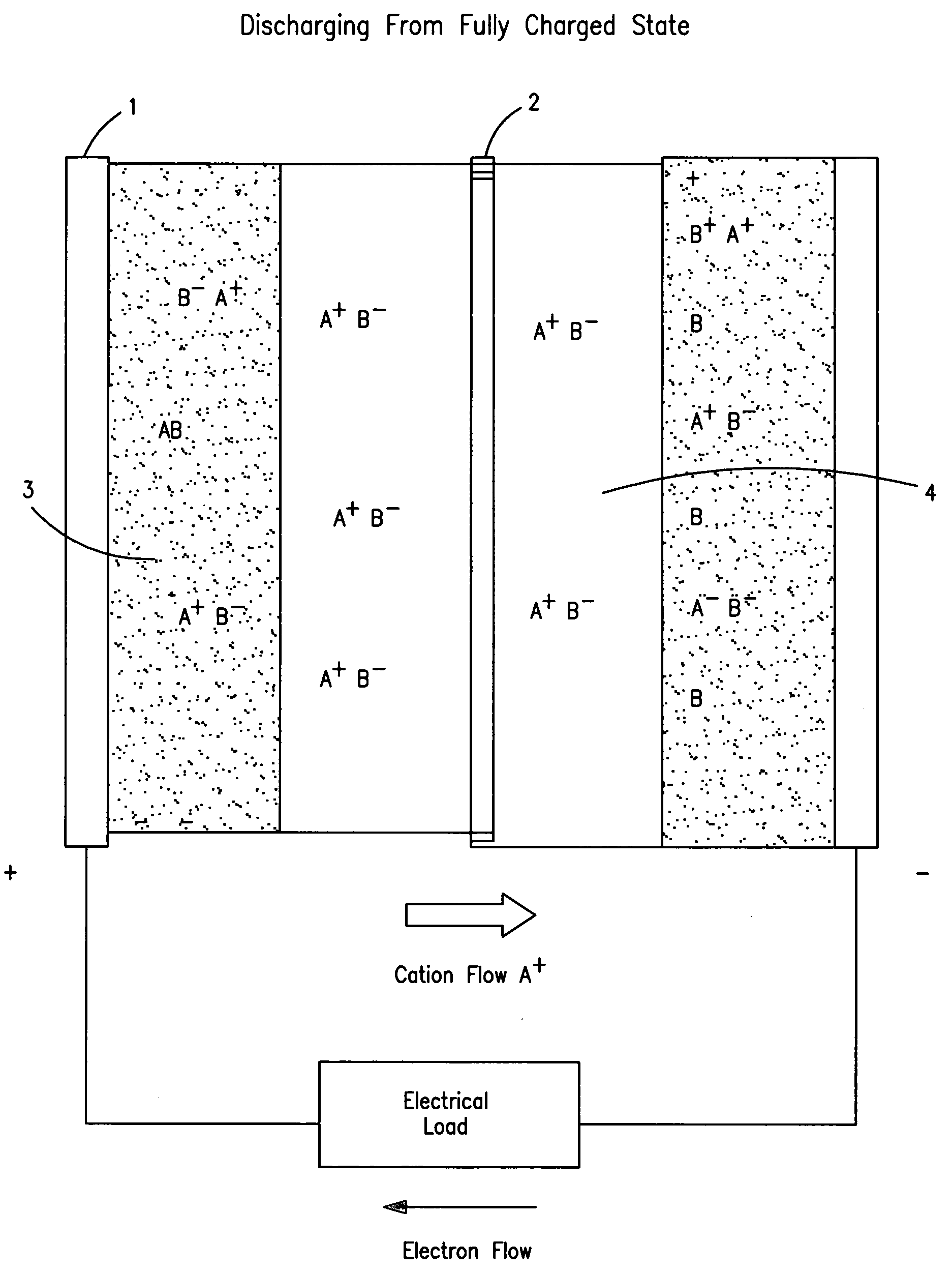
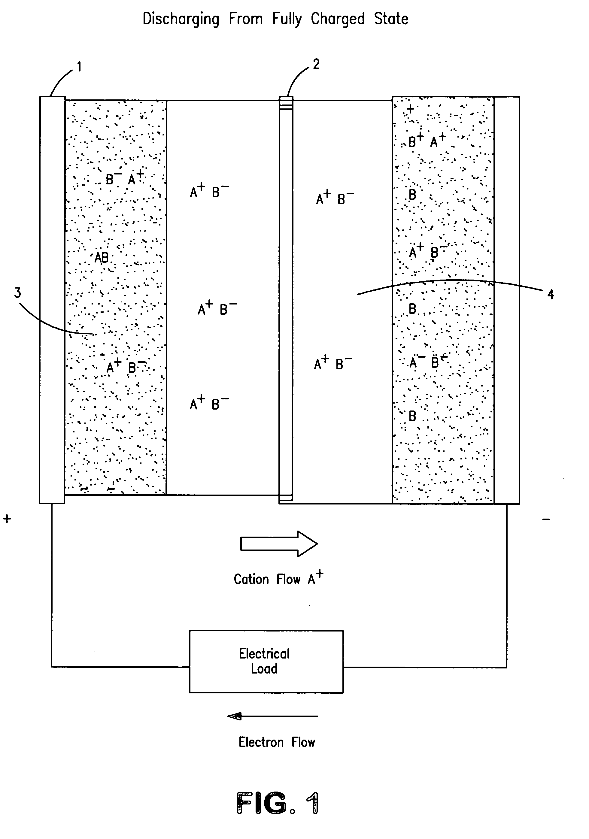
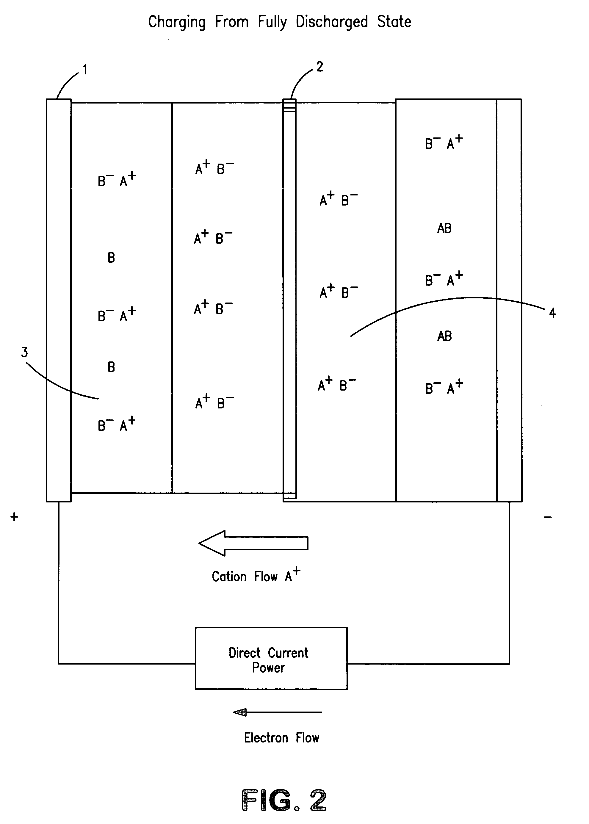
[0007]This invention is an electrochemical system for the storage of energy with essentially no irreversible inherent processes necessary to its operation that would result in inexorable deterioration of performance. The energy is stored in the form of concentration differences of a single chemical substance at opposite electrodes within an electrochemical cell. That substance is readily ionized and reduced or oxidized at the electrodes upon demand. The main performance goals are very long operational life, reproducibility and dependability of performance as well as low cost. Application possibilities considered are the electric hybrid car, emergency and portable power, load leveling for solar, wind and hydro sources. Problems normally associated with solid reagent materials in secondary electrochemical cells are virtually eliminated in this invention. And since the chemical environment is mild, there is deterioration of electrodes or other internal cell components. Any non-uniformity of electrolytic depositions in electrode surfaces during cycling is self-correcting.

Problems solved by technology

And since the chemical environment is mild, there is deterioration of electrodes or other internal cell components.
A microporous or cation exchange membrane serves that purpose well—but not quite well enough.

Method used


Image

  • Concentration cell energy storage device
  • Concentration cell energy storage device
  • Concentration cell energy storage device

Examples


example-1

[0120]Empirical performance data for the sulfide and iron cells are given in the following figurers.

[0121]FIG. 6 describes a few of a series of over 1,000 cycles put onto a sulfide cell with electrode area of 4 square inches and spacing of 0.20 inches on either side of a Sybron cation membrane. The reagents are stored at the electrode sites consisting of coconut, UU grade charcoal, loosely compacted between the electrodes and membrane. Reproducibility and consistency of cycling is noted. Active flat area of membrane and electrodes is 4 in2.

example-2

[0122]FIG. 7 shows two cycles for an iron concentration cell employing carbon felt pads mechanically laying against each of the two electrodes. A plastic (honeycomb structure) screen is between the felt pads on both sides to permit introduction of electrolyte in to cell after assembly. A sheet of RAI. Co. homogeneous polyethylene cation transport membrane referenced as ESC type. Electrode plate area is about 5 in2. The cycles, over 1200, are almost indistinguishable from each other in performance, and with no observable degradation.

[0123]FIG. 8 shows the continued cycling of the same cell-B to indicate the cycle reproducibility of electrical data. These last four cycles represent over 1,00 total energy events for that cell when discharging at constant resistive load.

example-3

[0124]More experimental data with sulfide cells are presented in the next graph. A cell is constructed, FIG. 9, employing Sybron (cation) membrane as separator principally to eliminate any electronic contact between charcoal particles on opposite electrodes. This cell has a flat electrode area of about 10 in2 and electrode plate separation of 0.5 in. The figure shows charge-discharge electrical characteristics while maintaining constant resistive load during discharge. The total (x-axis length) time for the cycling as shown in the graph is 25 hours. The reproducibility of characteristics from one cycle to the next is again demonstrated.

[0125]Details of Cell Fabrication

[0126]Construction of concentration cells is very similar to that of many electrochemical devices. In principle they consist of two electrodes, an internally intervening electrolyte and a physical separator that permits transport of ions for electrical conduction while presenting maximally obstructing flow or mixing of...


PUM


Abstract

A method and apparatus for the accumulation and storage of energy in electrically reversible manner wherein a two chamber electrochemical cell(a single one or part of an array of such cells) has an electrolyte of common specie solutions in the multi-chambers associated with cell electrodes and application of voltage to the electrodes causes dissimilar concentrations of ions in two chambers so that the energy is stored and reversing polarity of the electrodes allows energy discharge and normalization of concentration. Materials may be reversibly stored in the cell as solids when exceeding the solubility limits of the electrolyte, such storage being done preferably at porous electrode surfaces.

Description

FIELD AND BACKGROUND OF INVENTION[0001]The present invention relates to electrochemical energy storage and delivery devices.[0002]The need for a practical energy storage device is by now obvious to everyone. To date there is no inexpensive, reliable and light weight method of storing energy for use at a later time. Methods such as compressed air, metal springs, flywheels, and even batteries are too heavy, complex, unreliable and generally have short lives or high maintenance.[0003]Also, at present, there is no inexpensive means of storing energy for use in automobiles. The hybrid electric car presently employs lithium-ion cells for storage. However, they are too costly to provide a useable driving range, and are too heavy for practical use.[0004]The same situation exists regarding storage of large quantities of energy generated by wind mills, solar cells, or even hydroelectric plants for later use. This state of affairs continues to motivate me to search for a possible solution. Ene...

Claims


Application Information

Patent Timeline
IPC IPC(8): H01M6/24H01M4/66
CPCH01M4/38H01M4/621H01M4/663H01M4/667Y02E60/50H01M4/76H01M4/96H01M10/39H01M10/3909H01M4/70Y02E60/10
Inventor ZITO, RALPH
Owner ZITO RALPH
Learn More