Method for manufacturing heat transfer member, power module, vehicle inverter, and vehicle

a technology of heat transfer member and heat transfer plate, which is applied in the direction of electrical apparatus contruction details, lighting and heating apparatus, and semiconductor/solid-state device details. it can solve the problems of difficult uniform cooling of inability to uniformly cool coating film and base material, and oxidation of copper or alloy thereof. , to achieve the effect of reducing the difference in thermal expansion, and improving the fatigue strength of thermal cycles

Inactive Publication Date: 2010-09-16
TOYOTA JIDOSHA KK
View PDF7 Cites 17 Cited by
  • Summary
  • Abstract
  • Description
  • Claims
  • Application Information

AI Technical Summary

Benefits of technology

[0025]According to the present invention, the coating film of the heat transfer member is located between the insulating member included in the power module and the heat sink member. This eliminates the need to apply silicon grease hindering heat transfer, to the surface of the heat sink member. Thus, heat from the heated power element can be more suitably transmitted by the heat sink member. Moreover, the coating film has a porous structure and thus enables a reduction in the difference in thermal expansion between the insulating member and the heat sink member. As a result, fatigue strength associated with thermal cycles can be improved, thus enhancing the reliability of the power module.
[0026]Moreover, such a power module is preferably used for a vehicle inverter that needs to be composed of reliable devices. Furthermore, the heat transfer member manufactured by the manufacturing method offers high heat conductivity. Thus, the coating film can be effectively used for devices having a heat radiating structure, for example, engine parts of the vehicle and a CPU in an electronic apparatus.
[0027]The present invention provides a heat transfer member allowing the peel-off and cracking possibly caused by thermal expansion to be inhibited.

Problems solved by technology

Thus, the copper or the alloy thereof is severely oxidized.
However, uniformly cooling the coating film and base material is difficult.
A failure to uniformly cool the coating film and base material may vary the characteristics of the members.
However, even if a power module is manufactured by this method, the reliability of the power module cannot be sufficiently improved.
This may preclude the reliability of a power module and an inverter including the power module from being improved.

Method used


Image

  • Method for manufacturing heat transfer member, power module, vehicle inverter, and vehicle
  • Method for manufacturing heat transfer member, power module, vehicle inverter, and vehicle
  • Method for manufacturing heat transfer member, power module, vehicle inverter, and vehicle

Examples


example 1

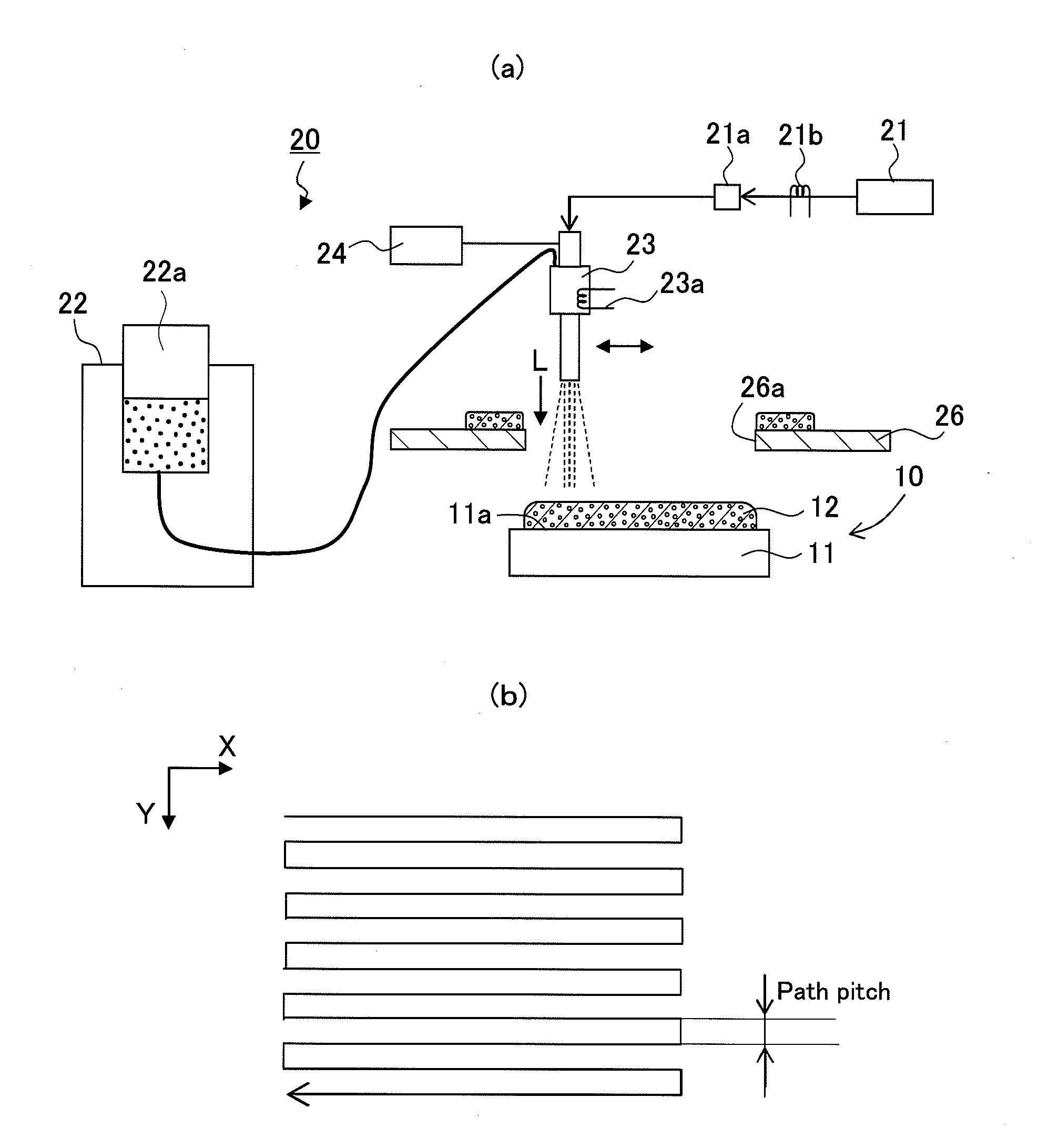
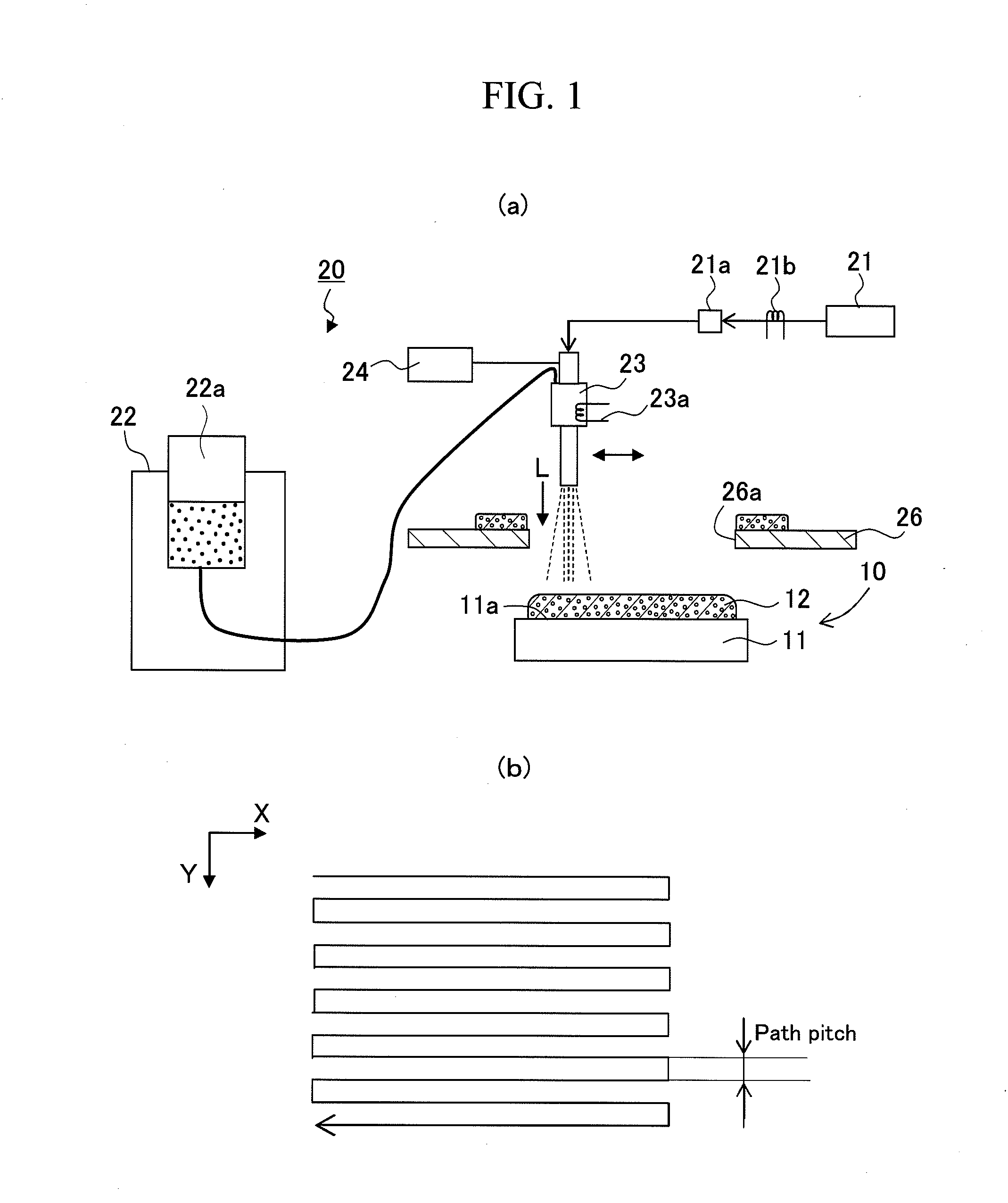
[0050]The cold spray method was used to produce a heat transfer member with a copper coating film formed on a base material. Specifically, a coating film made of copper powder was formed so as to have a density of 7.8 g / cm3 (12.4 vol % of vacancy) by compressing air (atmosphere) and spraying metal powder in the solid state made of copper, onto the surface of a heat sink member (base material) composed of aluminum alloy of size 30 mm×20 mm×thickness 5 mm (HS standard: A6063S-T1) together with the compressed air (compressed gas).

[0051]More specifically, a spraying nozzle was placed 30 mm above a heat sink member via a masking plate with an opening for masking having a size of 30 mm×20 mm. Copper powder of average grain size 20 μm was fed into a hopper and supplied to the nozzle at 0.2 g / s. On the other hand, air compressed to 0.6 MPa (compressed gas) was introduced into the nozzle and heated by a heater in the nozzle. The heated gas was then supplied with the copper powder. The copper...

example 2

[0054]As in the case of Example 1, a heat transfer member was produced. A difference from Example 1 was that after film formation, the heat transfer member was further thermally treated in an argon gas atmosphere under a temperature condition of 300° C. and one hour. As in the case of Example 1, the heat conductivity, coefficient of linear expansion, hardness, and Young's modulus of the thermally treated heat transfer member were measured. The results are shown in Table 1.

example 3

[0055]As in the case of Example 1, a heat transfer member was produced. A difference from Example 1 was that after film formation, the heat transfer member was further thermally treated in an argon gas atmosphere under a temperature condition of 600° C. and one hour. As in the case of Example 1, the heat conductivity, coefficient of linear expansion, hardness, and Young's modulus of the thermally treated heat transfer member were measured. The results are shown in Table 1. Furthermore, the surface structure of the coating film was observed as is the case with Example 1. The results are shown in FIG. 4(b).


PUM

PropertyMeasurementUnit
temperatureaaaaaaaaaa

Abstract

The present invention provides a method for manufacturing a heat transfer member which method allows peel-off and cracking possibly caused by thermal expansion to be inhibited. That is, the present invention provides a method for manufacturing a heat transfer member 10, the method at least including a step of forming metal powder into a coating film 12 on a surface of a base material 11 by spraying the metal powder in a solid state onto the surface of the base material 11 together with compressed gas. In the film forming step, a spraying pressure at which the metal powder is sprayed onto the surface of the base material 11 is set so that the coating film 12 has a porous structure.

Description

TECHNICAL FIELD [0001]The present invention relates to a method for manufacturing a heat transfer member in which metal powder in a solid state is sprayed onto the surface of a base material with compressed gas to form a coating film with the composition of the metal powder, a power module including the heat transfer member, a vehicle inverter including the power module, and a vehicle in which the vehicle inverter is mounted.BACKGROUND ART[0002]A power module 70 used in an inverter for a vehicle is conventionally composed of electronic components shown in FIG. 7. Specifically, the power module 70 includes at least a power element 71 composed of a silicon element, an insulating member 73 composed of aluminum nitride and to which the power element 71 is fixed via a solder layer 72, and a heat sink member 74 composed of aluminum. Moreover, a cushion member 75 composed of copper-molybdenum (Cu—Mo) or aluminum-silicon carbide (Al—SiC) is disposed between the insulating member 73 and the ...

Claims


Application Information

Patent Timeline
Patent Type & Authority Applications(United States)
IPC IPC(8): F28F7/00B05D3/10C25D5/48
CPCC23C24/04H01L21/4846Y10T29/4935H01L2224/32225H01L23/3735
Inventor TSUZUKI, YOSHIHIKOMIYAMOTO, NORITAKA
Owner TOYOTA JIDOSHA KK
Why Eureka
Try Eureka