Paint coating system

a coating system and paint technology, applied in the field of paint coating systems, can solve the problems of shortening the service life of the coating unit, and affecting the accuracy of the coating

Inactive Publication Date: 2010-09-16
ABB IND
View PDF5 Cites 29 Cited by
  • Summary
  • Abstract
  • Description
  • Claims
  • Application Information

AI Technical Summary

Benefits of technology

[0011]It is another object of the present invention to provide a paint coating system which is arranged to put a robot device in a reduced power mode at the time of gripping a common body of a coater unit, and thereby permitting to set the common body accurately at a predetermined changing position.
[0015]As a consequence, the atomizing head as well as the paint cartridge on the common body can be attached or detached quite smoothly in such away as to prolong their service life. Besides, it becomes possible to improve the work for installation of the robot device as well as machining operations and installation of the atomizing head changing and washing device and the paint cartridge changer. Furthermore, it becomes possible to cut the cost of a paint coating system as a whole.
[0023]In this case, at the time when the common body of the coater unit is gripped by the common body gripper, the robot device is switched to a reduced power mode, lowering driving forces of the robot device to a minimum necessary level for maintaining a required posture. As a result, the common body is virtually set in a free state and can be moved freely without disturbed by a robot device. Thus, even if there is a positional deviation between the robot device and the common body gripper, the common body of the coater unit can be accurately located and fixed in a changing position by the common body gripper which is arranged to modify a positional deviation of the coating unit if any.
[0025]With the arrangements just described, the common body gripper can orient the common body to a correct position in the radial direction by engagement with the grip portions of the common body at the time of gripping the common body of the coater unit. Therefore, by the common body gripper, the common body is located accurately in a specific changing position in a correctly oriented state.

Problems solved by technology

However, in the case of a robot device which is in use for paint coating operations, with regard to the repeated positioning accuracy in motion control such as moving, stopping, posture and the like of a coater unit which is mounted on a distal end of a robot arm, there is inevitably an error of several millimeters.
Therefore, if the changing operation is carried out depending upon the accuracy of motion control on the part of the robot device alone, this deviation from the predetermined changing position may result in exertion of a forcible load between a common body and the atomizing head or the paint cartridge, shortening the service life of the coater unit by repeated abrasive and damaging contact.

Method used


Image

  • Paint coating system
  • Paint coating system
  • Paint coating system

Examples


Embodiment Construction

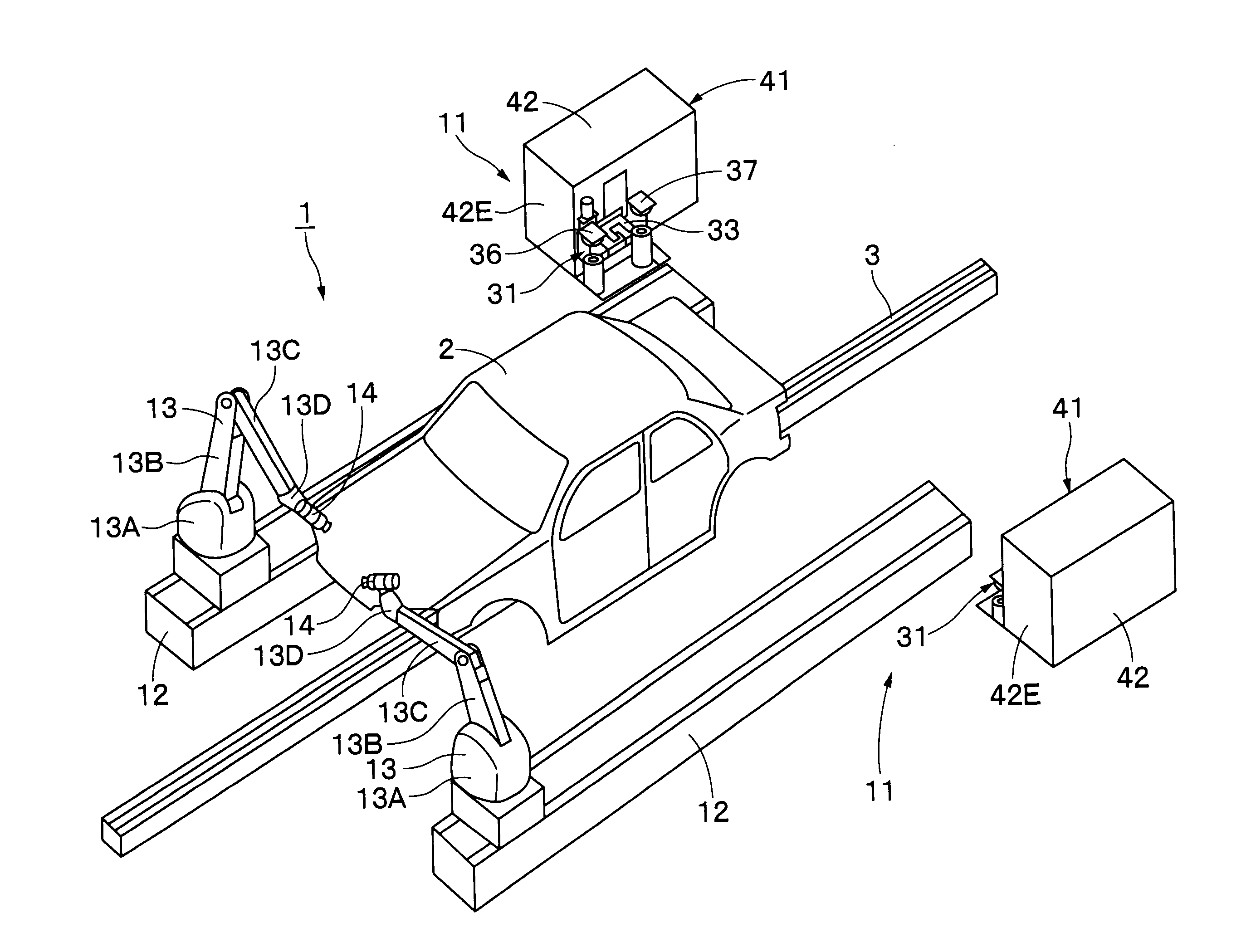
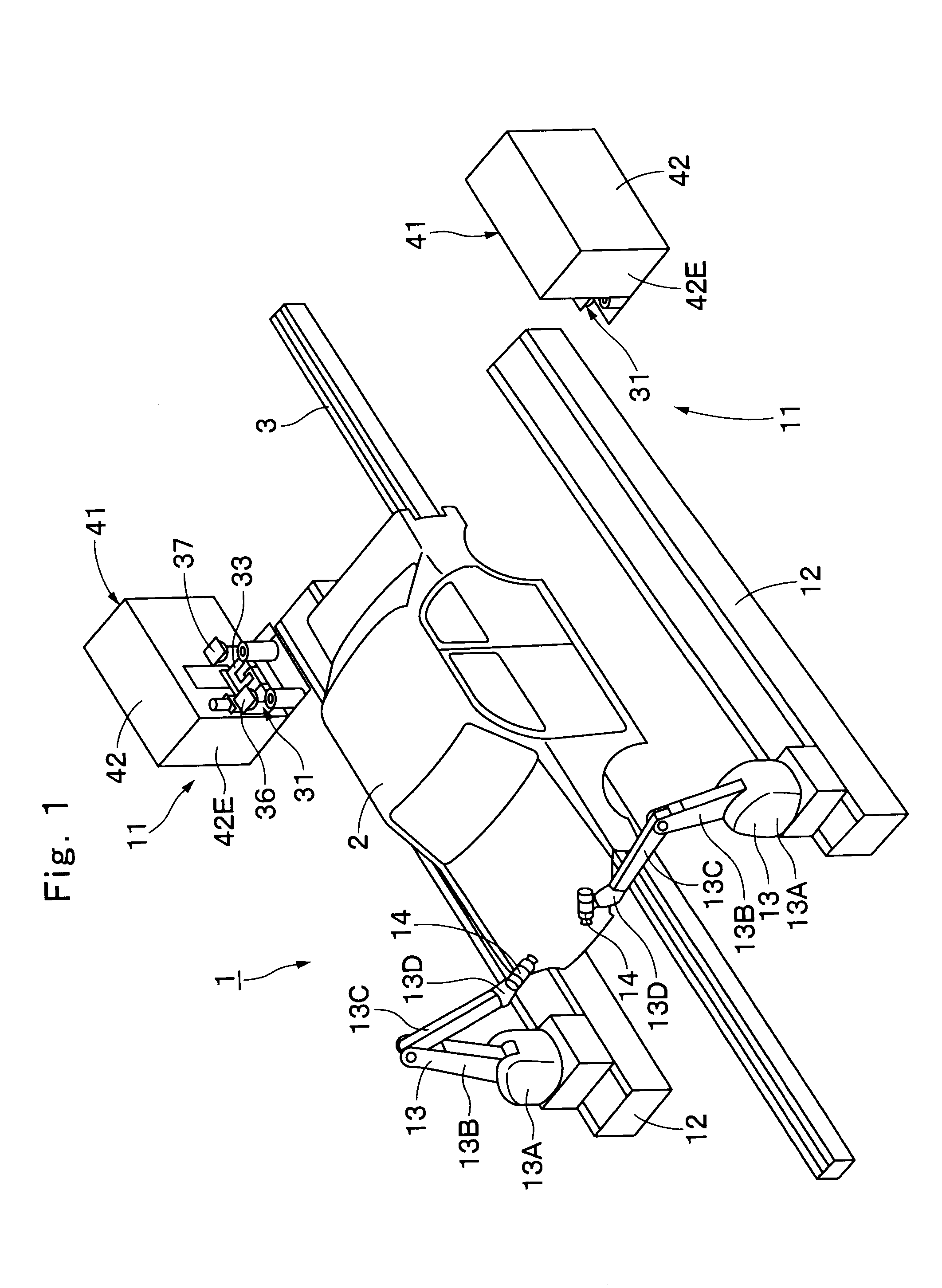
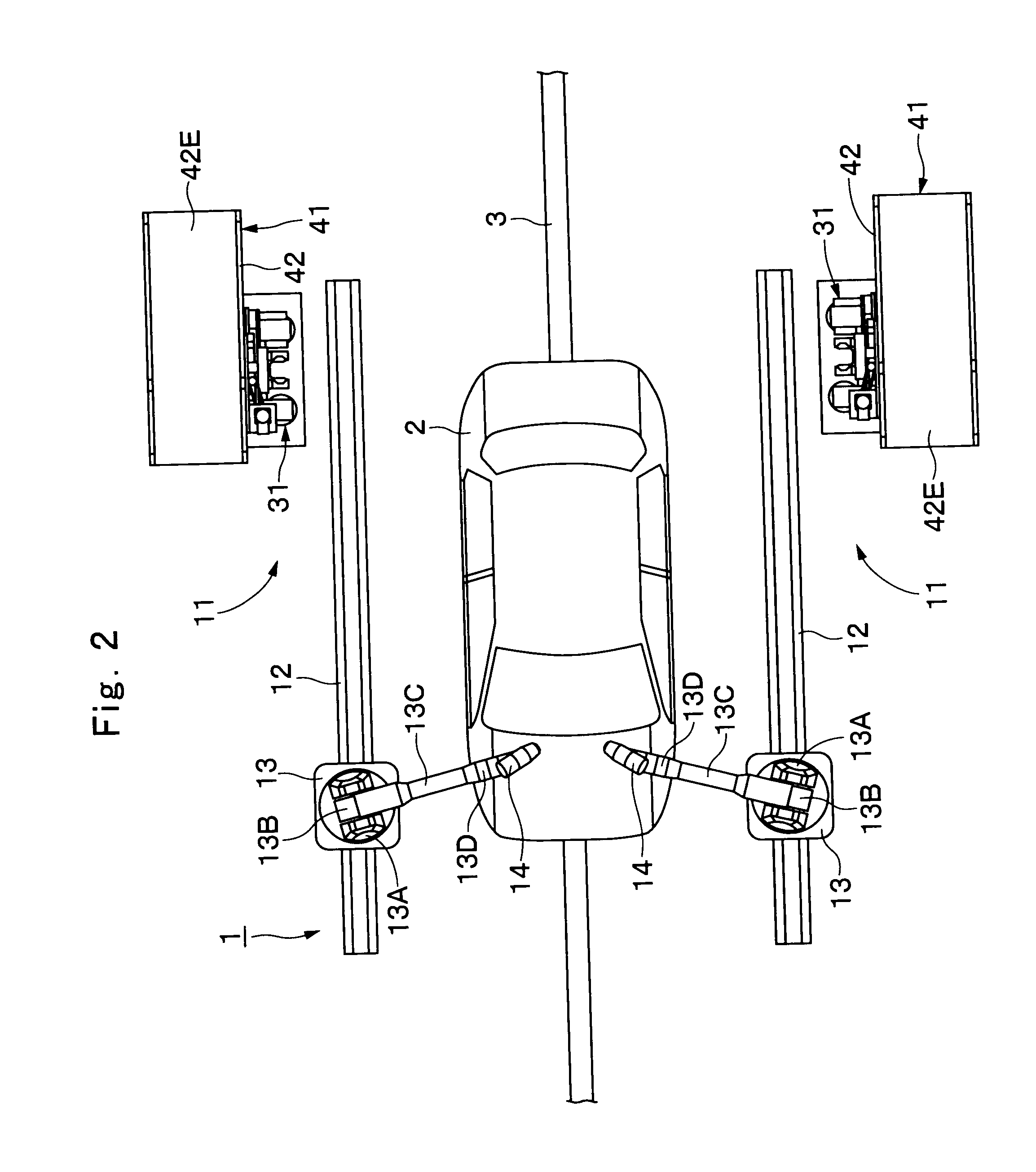
[0071]Hereafter, with reference to FIGS. 1 through 40, the paint coating system of the present invention is described more particularly by way of its preferred embodiment which is applied as a vehicle body painting system, for example.

[0072]In FIGS. 1 and 2, indicated at 1 is a coating line for coating a vehicle body 2. Moreover, at the half way of the conveyer 3, paint coating system 11, which will be described hereinafter, are located on the opposite side of the conveyer 3.

[0073]Indicated at 11 are paint coating systems which are located at the half way and cooperatively on the opposite sides of the conveyer 3. Each one of the paint coating systems 11 is largely constituted by a robot device 13, a coater unit 14, an atomizing head changing and washing device 31, and a cartridge changer 41, which will be described hereinafter.

[0074]Designated at 12 are tracking rails which are located in predetermined transversely spaced positions on the opposite side of the conveyer 3 in parallel ...


PUM


Abstract

A common body (15) of a coater unit (14) is mounted on a robot device (13). A common body gripper (33) is fixedly mounted on a fixed plate (32) of an atomizing head changing and washing device (31). At the time of replacing a used atomizing head (19′) and a used paint cartridge (24′) by a washed atomizing head (19) and a replenished paint cartridge (24), respectively, the common body (15) is gripped and located in a predetermined position by the common body gripper (33). When the common body (15) is gripped by the common body gripper (33), the robot device (13) is put in a reduced power mode attenuating driving forces to leave said common body (15) in a freely movable state by application of an external force.

Description

TECHNICAL FIELD[0001]This invention relates to a paint coating system particularly suitable for use, for example, in coating vehicle bodies, furniture, electric appliances and the like.BACKGROUND ART[0002]Generally, paint coating systems in use for painting vehicle bodies and the like are largely constituted by a robot device with an articulated arm, and a coater unit mounted on a distal end of the robot arm of the robot device and provided with an atomizing head for spraying atomized paint particles.[0003]Among paint coating systems of this sort, there is a system providing a plural number of atomizing heads which can be replaceably attached to a common body which is mounted on a distal end of a robot arm of the robot device (see, for example, Patent Literature 1: Japanese Patent Laid-Open No. 2001-79463). In another paint coating system, paint cartridges filled with paint, which is supplied for atomizing heads, are interchangeably attached to the common body (see, for example, Pat...

Claims


Application Information

Patent Timeline
Patent Type & Authority Applications(United States)
IPC IPC(8): B05B15/02B05B12/00B05B12/14B05B15/06B05B15/10B05B16/00
CPCB05B5/0407B05B5/0426B05B5/1625B05B5/1675B05B12/1463B05B13/0431B25J15/0491B05B15/0258B05B15/061B05B15/1292B25J9/0084B25J9/0093B05B13/0452B05B15/555B05B15/62B05B16/95B05B3/00
Inventor UMEZAWA, TOKUOMATSUDA, HIDETSUGUKUROMOTO, MASAHARUSAKATA, YUTAKA
Owner ABB IND
Why Eureka
Try Eureka