
Solid propellant/liquid type hybrid gas generator

a hybrid gas generator and solid propellant technology, applied in the direction of pedestrian/occupant safety arrangement, vehicular safety arrangment, vehicle components, etc., can solve the problems of low molecular weight halogen compounds (including hcl and hf), water spraying, and small modification, and achieve efficient use of cooled gas and high yield

Inactive Publication Date: 2010-09-16
ARC AUTOMOTIVE
View PDF11 Cites 25 Cited by
  • Summary
  • Abstract
  • Description
  • Claims
  • Application Information

AI Technical Summary

Benefits of technology

[0010]It is an object of the present invention to provide a gas generating device for airbags and the like, which achieves thorough mixing of the pyrotechnic combustion gas and liquid that results in an efficient cooled gas high yield and which therefore achieves an efficient use thereof.
[0011]It is a further object of this invention to provide such a gas generating device which maintains the coolant liquid at a temperature above its freezing point and thus maintains the device properly operable irrespective of the climate in which the safety device associated with the gas generator is used.
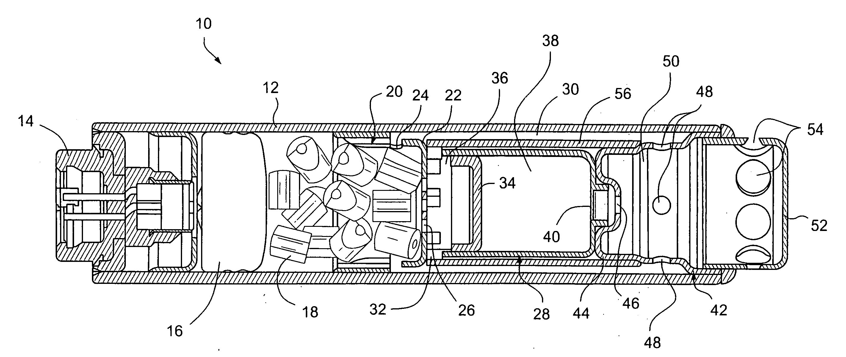
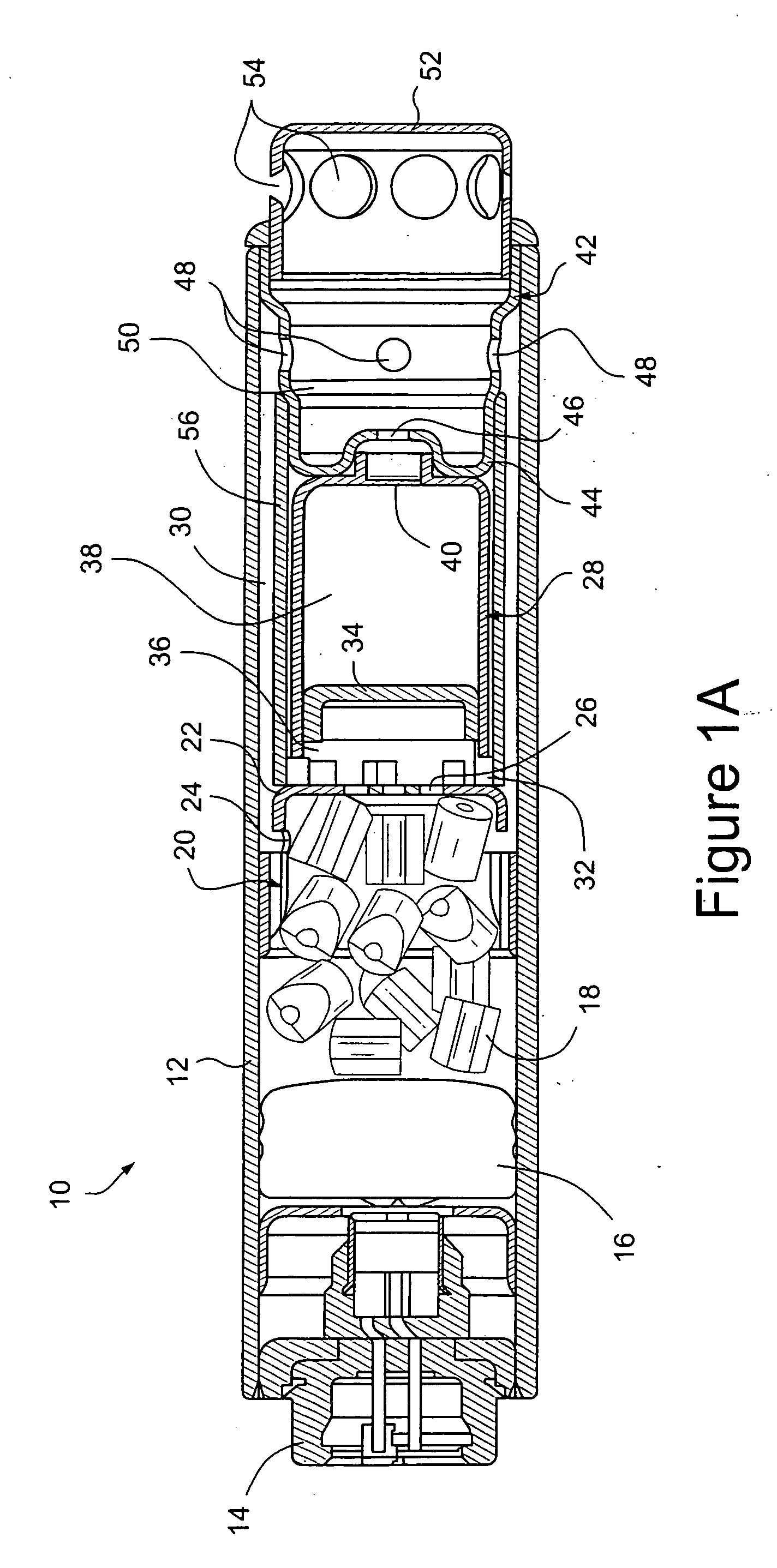
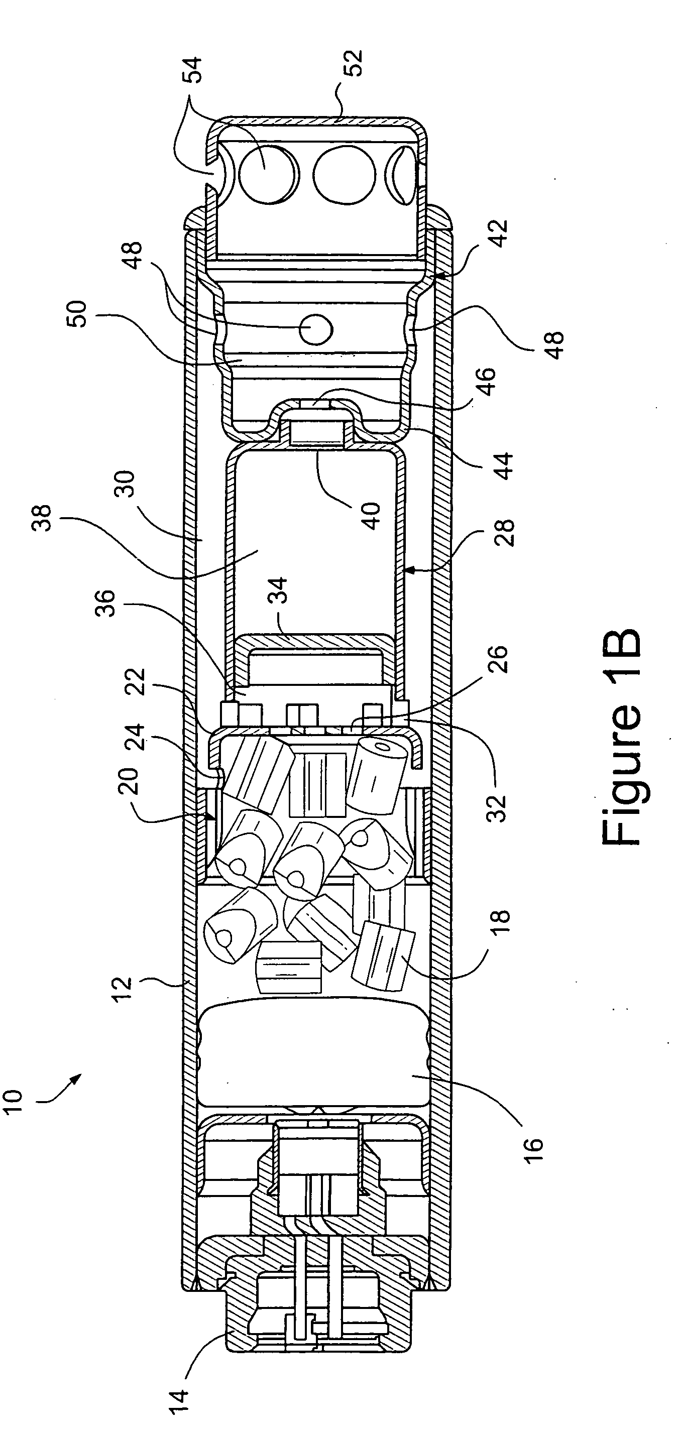
[0016]In the operation of the one embodiment, the actuation of the igniter causes ignition of the booster charge and the propellant to generate combustion gas that flows out of the first peripheral orifices in the partition, through the annular flow channel surrounding the chamber tube and into the mixing chamber through the peripheral third orifices in the inner housing member at the end of the housing. The combustion gases also flow axially through the second orifice or orifices in the inner end of the partition to create sufficient pressure against the adjacent chamber cap to cause it to separate from the chamber tube and move inwardly therein to pressurize the liquid in the chamber tube. The increased pressure in the chamber tube causes the weakened portion at the closed end thereof to open to allow the pressurized liquid to flow into the mixing chamber through the aperture in the adjacent inner end of the inner housing member.

Problems solved by technology

However, many of these arrangements have simply released the hot combustion products into the inflatable device with very little modification other than filtering to remove particulate matter.
The decomposition of halocarbon results in the formation of lower molecular weight halogen compounds (including HCl and HF), which are toxic.
However, this arrangement is such that a slug of unvaporized liquid is apt to be shot out of the device only to result in the water being sprayed like a shower of rain throughout the interior of the airbag.
Thus, while these arrangements may find application as fire extinguishers of the nature disclosed in U.S. Pat. No. 5,449,041 issued on Sep. 12, 1995 in the name of Galbriath, wherein a solid propellant charge is ignited and used to drive a volume of liquid having flame suppressing capabilities, against a fire in a manner which suppresses and extinguishes it, they have failed to make the most efficient use of the cooling effect possible with the liquid used.
Another problem that these arrangements have failed to address is that of low temperature climates in which liquids, such as water, are apt to freeze and thus fail to achieve cooling of any degree, and / or even hinder the operation of the device by generating a block of solid material (ice) that is apt to either block the exits or turn into a missile which is fired out of the device in a highly undesirable manner.
The above problem is further aggravated in that the use of halocarbon liquids, which would tend to alleviate the freezing problem, are now severely restricted in light of various environmental considerations.

Method used


Image

  • Solid propellant/liquid type hybrid gas generator
  • Solid propellant/liquid type hybrid gas generator
  • Solid propellant/liquid type hybrid gas generator

Examples


Embodiment Construction

[0027]FIG. 1A shows one embodiment of the present invention in the form of a gas generator 10 that may be used as a side impact or other inflator for an airbag or the like. The gas generator 10 comprises an elongated, generally cylindrical housing 12 formed of any suitable metal or other material having an igniter 14 of any suitable type at one end thereof. A booster charge 16 of any suitable type is disposed inwardly of the igniter 14 and a pyrotechnic charge or solid propellant 18 of any suitable type is disposed inwardly of the booster charge 16. A cup-like partition 20 surrounds the inner portion of the pyrotechnic charge or propellant 18 and has a reduced diameter end portion 22 with a plurality of first orifices 24 in the periphery thereof and a second orifice or orifices 26 in the inner end thereof.

[0028]A chamber tube 28 is disposed in the housing 12 inwardly of the end portion 22 of the partition 20 and is of a diameter less than the internal diameter of the housing 12 to p...


PUM


Abstract

A gas generator comprising a housing having a mixing chamber and a pyrotechnic charge in the housing. A container having a liquid therein is disposed in the housing and has an open end and a closed end, with an end cap closing the open end and having a piston portion removably connected thereto and being movable within the liquid container to pressurize the liquid therein when the piston portion is separated from the end cap. The piston portion is positioned to be exposed to combustion gas from the pyrotechnic charge when it is ignited and is separable from the end cap when the combustion gas exceeds a predetermined pressure. In another embodiment, the liquid container may be a collapsible tube. The closed end of the liquid container has a weakened portion constructed to be opened when the pressure of the liquid in the container exceeds a predetermined pressure. The pyrotechnic charge and the weakened portion of the liquid container are in fluid communication with the mixing chamber so that combustion gases from the ignition of the pyrotechnic charge mix with and vaporize the liquid in the mixing chamber to generate a non-toxic, low temperature, low particulate inflation gas.

Description

BACKGROUND OF THE INVENTION[0001]1. Field of the Invention[0002]The present invention relates generally to a gas generating device and more specifically, to a gas generating device which mixes liquid with the hot gaseous combustion products of a solid propellant or pyrotechnic charge.[0003]2. Description of the Related Art[0004]Various gas generating arrangements have been proposed for the purposes of inflating a safety restraint device such as an airbag. However, many of these arrangements have simply released the hot combustion products into the inflatable device with very little modification other than filtering to remove particulate matter.[0005]In order to modify the gaseous products which are generated by the combustion of a solid propellant such as sodium azide mixed with an oxidizer such as potassium perchlorate, it has been proposed in U.S. Pat. No. 3,785,674 issued on Jan. 15, 1974 to Poole et al. to include a coolant chamber in the gas generator and to fill this chamber w...

Claims


Application Information

Patent Timeline
IPC IPC(8): B60R21/264B60R21/26
CPCB60R2021/26017B60R21/2644B60R21/26B60R21/272
Inventor ROSE, JAMES MICHAELHERRIFORD, LAWRENCE EDWARDGOLD, STEPHEN CRAIGTHOMAS, BRIAN ORGYLEWILKINS, JUDAH LEEISBELL, ROBB CALVIN
Owner ARC AUTOMOTIVE
Learn More