
Method for manufacturing liquid discharge head

Inactive Publication Date: 2010-09-16
CANON KK
View PDF5 Cites 5 Cited by
  • Summary
  • Abstract
  • Description
  • Claims
  • Application Information

AI Technical Summary

Benefits of technology

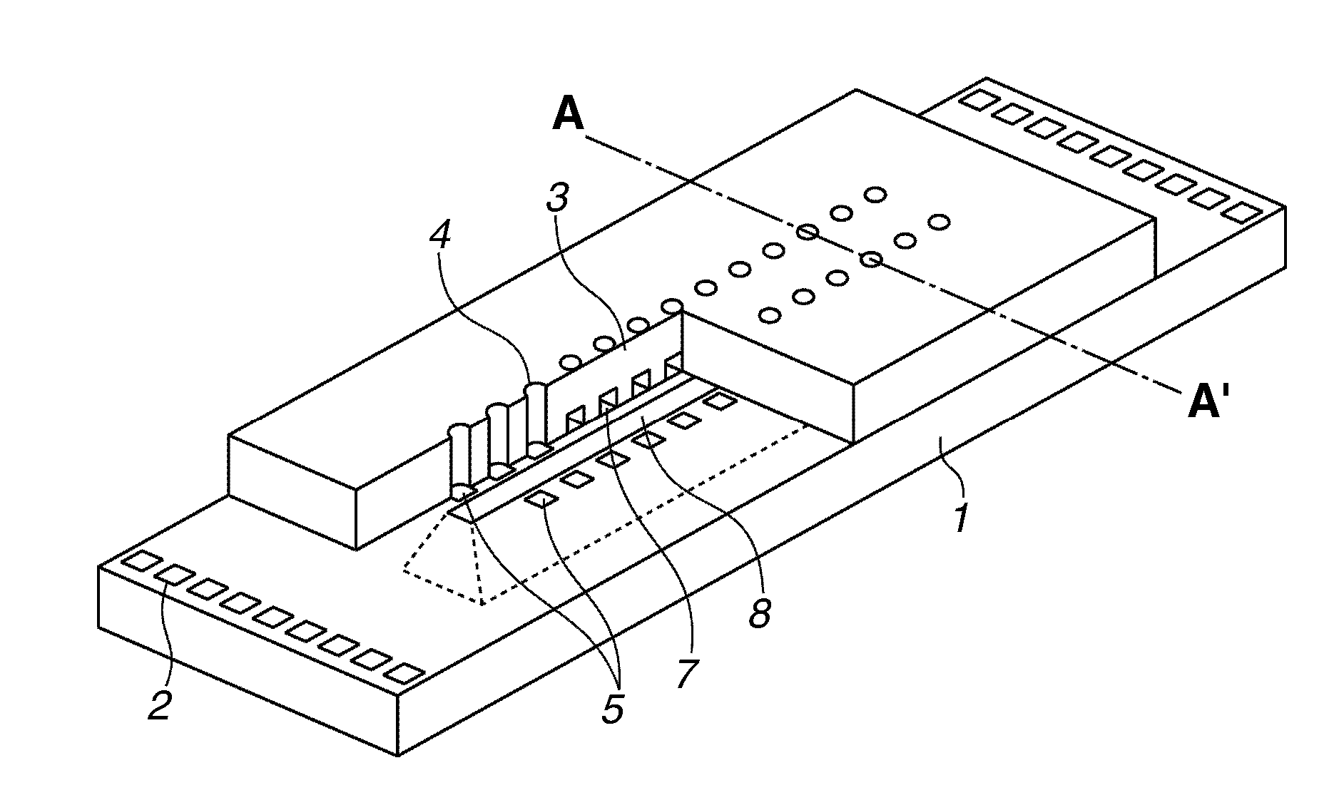
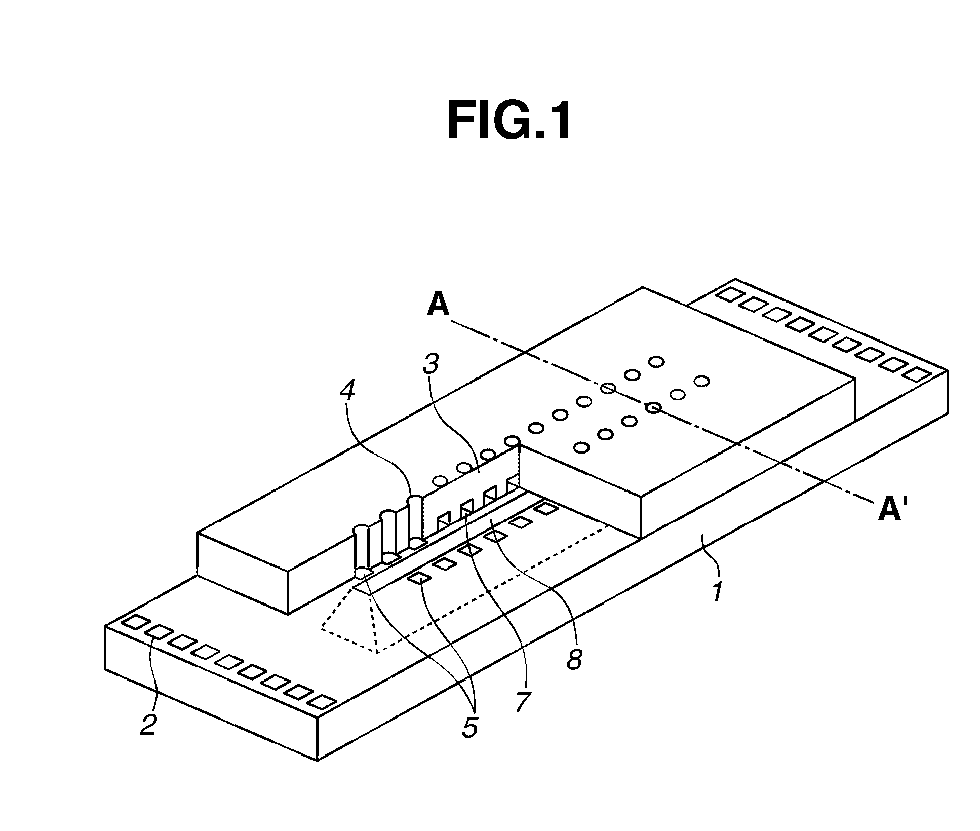
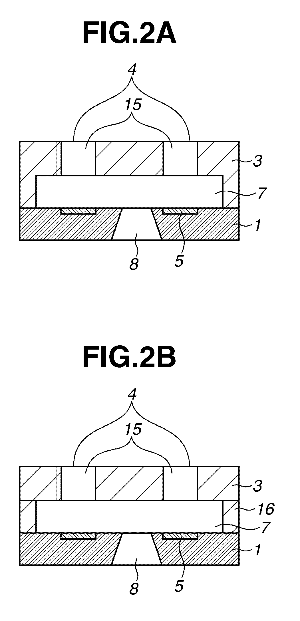
[0011]The present invention is directed to a method for manufacturing a liquid discharge head which can accurately form a pattern of a mold of a flow path on a desired position of a substrate, and can accurately acquire a desired shape of a discharge port.
[0013]According to an exemplary embodiment of the present invention, the method for manufacturing the liquid discharge head can control a position relationship among an energy generating unit, an ink flow path, and a discharge port on a substrate with high accuracy and high reproducibility, and can reproducibly produce a liquid discharge head which has excellent printing characteristic.

Problems solved by technology

However, the method for manufacturing a liquid discharge head discussed in U.S. Patent Publication No. 2007 / 0099121 has the following problems.
Since an exposure apparatus collectively exposes a large object (a positive photosensitive resin) provided on a substrate, positioning accuracy between the object and a mask used for exposing is insufficient.
However, the main chain decomposition type positive photosensitive resin mostly has low sensitivity to ultraviolet light, so that the exposure apparatus needs to emit a large amount of energy to generate an enough decomposition reaction.
Therefore, non-uniform heat expansion is caused between the mask and the substrate by the heat generation during an exposure operation, and resolution and alignment accuracy thus could be decreased.
As a result, position deviation between the energy generating unit and the pattern that becomes the flow path occurs, and the pattern of the flow path may not be formed at a desired position of the substrate.
On the other hand, inventors found out in examination that the method described in U.S. Patent Publication No. 2007 / 0099121 may not form a discharge port having a desired shape when the discharge port is formed at the flow path wall member by using i-line light.

Method used


Image

  • Method for manufacturing liquid discharge head
  • Method for manufacturing liquid discharge head
  • Method for manufacturing liquid discharge head

Examples


Embodiment Construction

[0021]Various exemplary embodiments, features, and aspects of the invention will be described in detail below with reference to the drawings.

[0022]In the following descriptions, configurations which have same functions are denoted by the same reference numerals in the drawings, and description thereof may be omitted.

[0023]A liquid discharge head can be applied to an ink jet recording head used in an ink jet recording system. However, an applicable scope of the present invention is not limited to the ink jet recording head. The present invention can be applied to biochip manufacturing and electronic circuit printing.

[0024]The liquid discharge head can be installed in a printer, a copying machine, a facsimile including a communication system, a device such as a word processor including a printing unit, and an industrial recording apparatus in which various kinds of processing devices are complexly combined. For example, the liquid discharge head can be used for biochip manufacturing, ...


PUM


Abstract

A method for manufacturing a liquid discharge head that includes a flow path wall member which forms a wall of a flow path communicating with a discharge port for discharging a liquid and a substrate which forms the flow path in contact with the flow path wall member includes providing a first layer, which is made of a photosensitive resin on the substrate, for forming a pattern having a shape of the flow path, providing a second layer which is capable of absorbing light within a photosensitive wavelength range of the photosensitive resin and has a shape corresponding to the shape of the flow path, on the first layer so as to come into contact with the first layer, performing patterning of the first layer which includes exposure of the first layer with the light using the second layer as a mask, and forming the pattern from the first layer, providing a cover layer which is made of a photosensitive resin and serves as the flow path wall member so as to cover the second layer and the pattern, forming the discharge port on the cover layer by performing patterning of the cover layer which includes exposure of the cover layer with the light, and forming the flow path by removing the second layer and the pattern.

Description

BACKGROUND OF THE INVENTION[0001]1. Field of the Invention[0002]The present invention relates to a method for manufacturing a liquid discharge head for discharging a liquid, and more particularly, to a method for manufacturing an ink jet recording head for performing recording by discharging ink to a recording medium.[0003]2. Description of the Related Art[0004]An ink jet recording head employed in an ink jet recording system is an example of a liquid discharge head used for discharging a liquid. The ink jet recording system discharges ink to a recording medium and performs recording. The ink jet recording head includes an ink flow path, a discharge energy generation unit provided at apart of the ink flow path, and a minute ink discharge port (it is referred to as an orifice) for discharging ink by generated energy.[0005]U.S. Patent Publication No. 2007 / 0099121 discusses a method for manufacturing such a liquid discharge head. In the method, a pattern layer, which is a mold for a fl...

Claims


Application Information

Patent Timeline
IPC IPC(8): G03F7/20
CPCB41J2/1603B41J2/1626B41J2/1645B41J2/1639B41J2/1631
Inventor WATANABE, MAKOTOTAGAWA, YOSHINORIIBE, SATOSHIASAI, KAZUHIROOHSUMI, MASAKINAGAI, MASATAKA
Owner CANON KK
Learn More