
Emulsion fuel and process and equipment for the production of the same

a technology of emulsion fuel and process, which is applied in the direction of machines/engines, mechanical equipment, transportation and packaging, etc., can solve the problems of impaired combustion efficiency, soot or black smoke generation, etc., and achieves improved combustion efficiency, efficient dissolution, and increased oxygen dissolved in the fuel oil

Inactive Publication Date: 2010-09-23
MG GROW UP CORP +1
View PDF4 Cites 12 Cited by
  • Summary
  • Abstract
  • Description
  • Claims
  • Application Information

AI Technical Summary

Benefits of technology

"The present invention provides an emulsion fuel with fine air bubbles that can improve combustion efficiency and stability. The emulsion fuel can be produced by mixing a fuel oil and water with a fluid mixer, and then adding a small amount of air to the mixture. The fine air bubbles can be formed by treating the fuel oil and water to be mixed with each other, and then adding a slight amount of air to the mixture. This process allows for a more complete mixing of the fuel oil and water, resulting in a more stable emulsion fuel."

Problems solved by technology

However, the above-described process for the production of emulsion fuel constitutes merely stirring / mixing a fuel oil and water by one mixer, thus entailing a disadvantage that: in the obtained emulsion fuel, water droplets condense, allowing dispersion of water droplet sizes to be non-uniform; and further, if the emulsion fuel is combusted by means of combustion equipment, the combustion efficiency becomes impaired, and soot or black smoke is generated.

Method used


Image

  • Emulsion fuel and process and equipment for the production of the same
  • Emulsion fuel and process and equipment for the production of the same
  • Emulsion fuel and process and equipment for the production of the same

Examples


first embodiment

Description of Equipment for the Production of Emulsion Fuel, as a First Embodiment

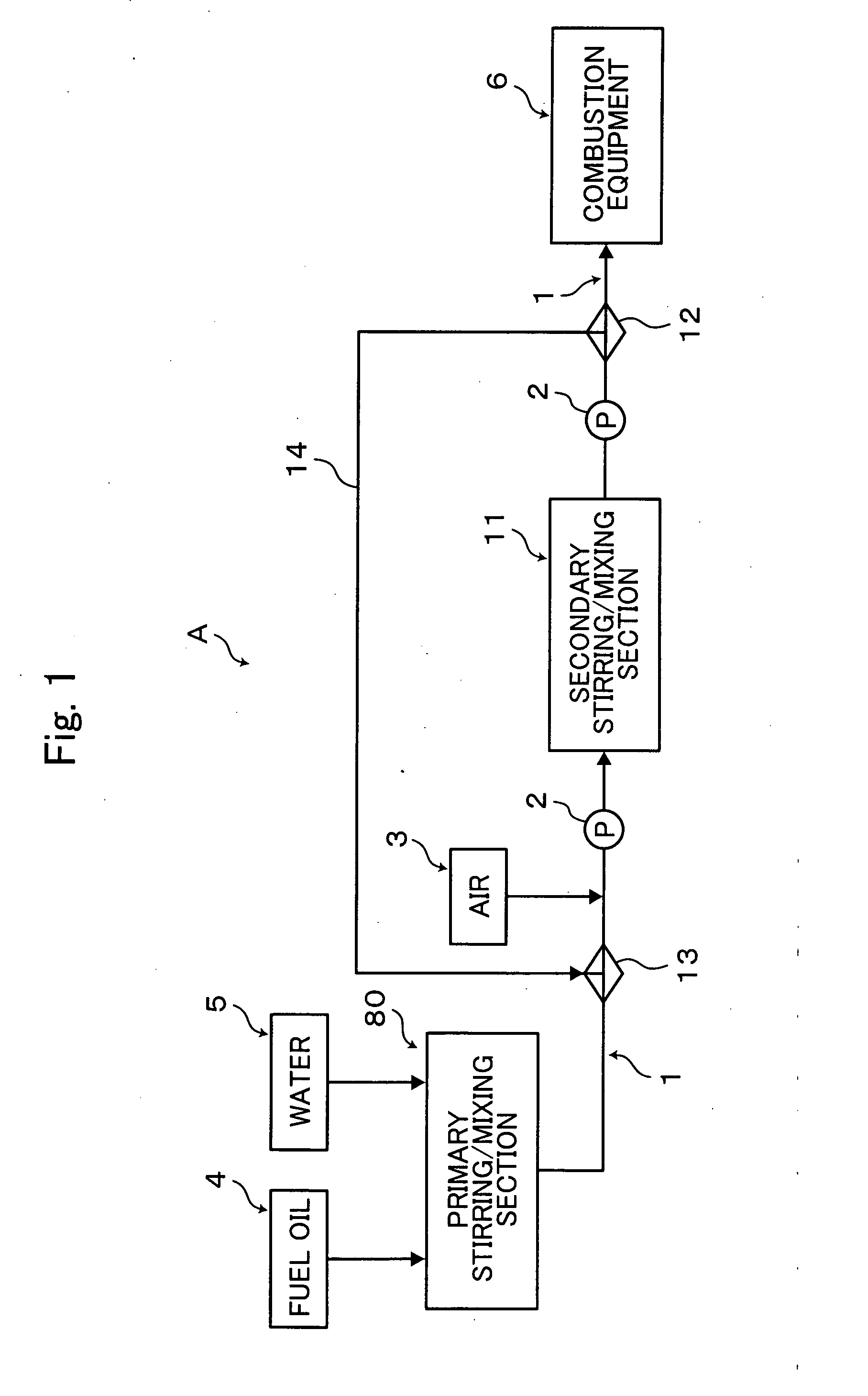
[0116]FIG. 1 is a conceptual view of equipment A1 for the production of emulsion fuel, as a first embodiment according to the present invention (hereinafter, referred to as “the first equipment”). The first equipment A1, as shown in FIG. 1, is provided with: a rotary stirring mixer 80 as a primary mixing treatment section for preliminarily uniformly stirring / mixing a fuel oil and water; and a stationary fluid mixer 11 as a secondary mixing treatment section for further stirring / mixing the stirred / mixed liquid mixture by means of the rotary stirring mixer 80. Both of the mixers 80, 11 are connected in communication with each other via a communication pipe 1 as a communication section so as to pressure-feed a predetermined amount of a primary treatment liquid from the rotary fluid mixer 80 to the stationary fluid mixer 11 by means of a pressure-feed pump which is provided at a midcourse part of the comm...

second embodiment

Description of Equipment for the Production of Emulsion Fuel, as a Second Embodiment

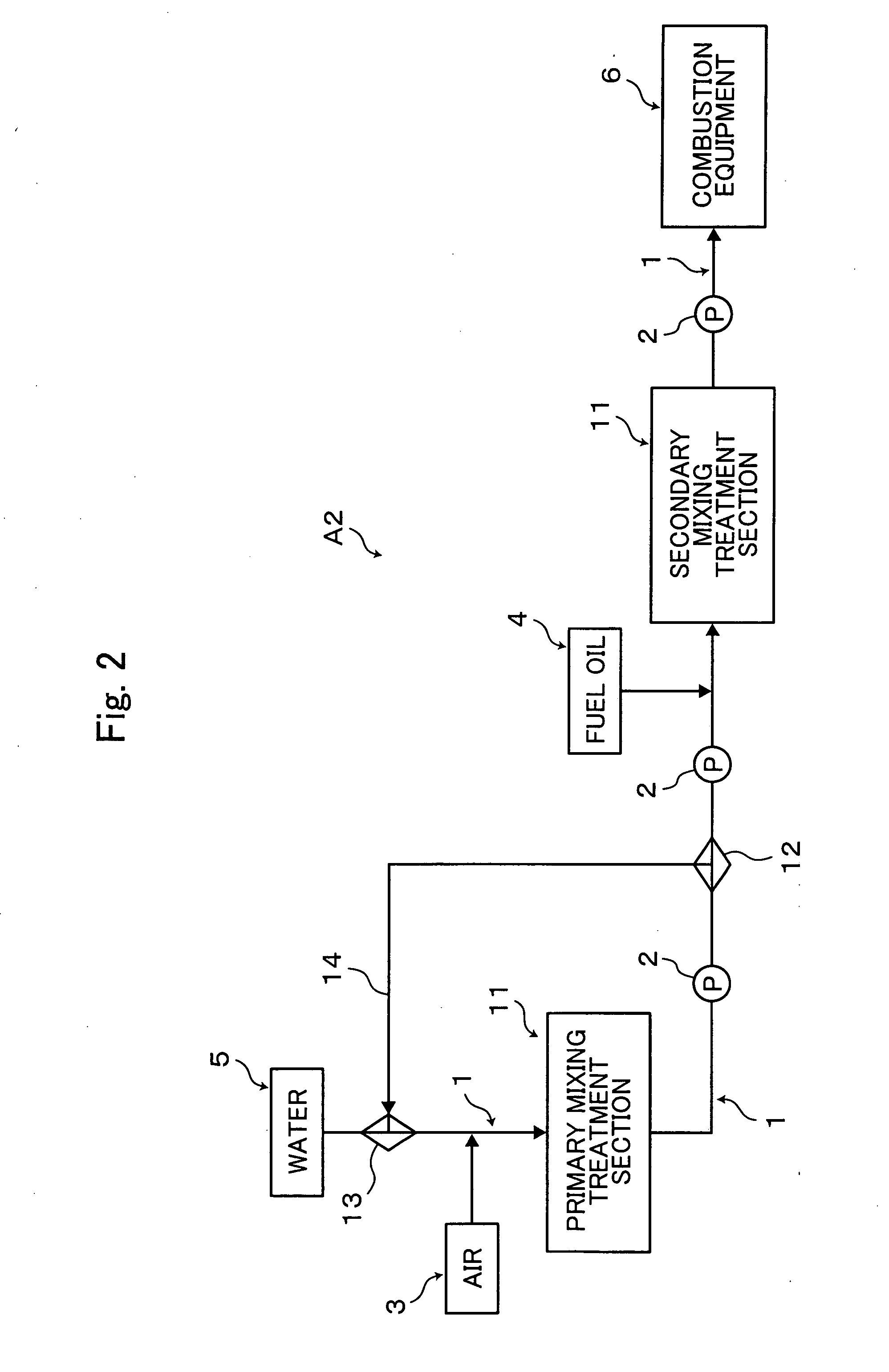
[0131]FIG. 2 is a conceptual view of equipment A2 for the production of emulsion fuel, as a second embodiment according to the present invention (hereinafter, referred to as “the second equipment”). The second equipment A2, as shown in FIG. 2, allows a water feed section 5 to be connected in communication with a stationary fluid mixer 11 as a primary mixing treatment section, via a communication pipe 1; a proximal end part of a suction pipe 3 to be connected in communication with a midcourse part of the communication pipe 1 and a distal end part of the suction pipe 3 to be opened in the ambient air. In addition, a stationary fluid mixer 11 as a secondary mixing treatment section is connected in communication with the abovementioned stationary fluid mixer 11, via a communication pipe 1; a pressure-feed pump 2 is provided at a midcourse part of the communication pipe 1; and an oil feed section 4 is con...

fourth embodiment

Description of Equipment for the Production of Emulsion Fuel, as a Fourth Embodiment

[0141]FIG. 4 is a conceptual view of equipment A4 for the production of emulsion fuel, as a fourth embodiment according to the present invention (hereinafter, referred to as “the fourth equipment”). The fourth equipment A4, as shown in FIG. 4, is provided with: a rotary stirring mixer 80 as a third mixing treatment section to be connected in communication with the stationary fluid mixer 11 as the secondary mixing treatment section of the aforementioned second equipment A2 via a communication pipe 1; a pressure feed pump 2 to be provided at a midcourse part of the communication pipe 1; and an oil feed section 4 to be connected in communication with a portion of the communication pipe 1, which is positioned at a downstream side of the pressure-feed pump 2.

[0142]In this manner, in the fourth equipment A4, in the primary mixing treatment course, water and air are treated to be mixed with each other by me...


PUM

PropertyMeasurementUnit
volume ratioaaaaaaaaaa
diametersaaaaaaaaaa
diameteraaaaaaaaaa

Abstract

An emulsion fuel is provided which is usable as a fuel for combusting an internal combustion engine under an appropriate combustion condition. A slight amount of air is added to, and is mixed with, a liquid mixture between a fuel oil as a continuous phase and water as a dispersed phase. In this manner, since air bubbles reduced in buoyancy is hydrophobic, the air bubbles do not adhere the surfaces of water droplets, and are dispersed in the fuel oil, increasing a gas-liquid interfacial area (combustion surface area) and exerting surface activity (similar to the function of a surfactant) due to electrostatic polarization. This makes it possible to prevent the coalescence of fine water droplets and stabilize the water droplets in the emulsion fuel. As a result, in the emulsion fuel, dispersion of water droplet diameters is homogenized, and even if the emulsion fuel is combusted by means of combustion equipment, for example, good combustion efficiency can be ensured, and further, a disadvantage that soot or black smoke is generated can be eliminated.

Description

[0001]The present invention relates to an emulsion fuel and process and equipment for producing the same continuously.BACKGROUND OF THE INVENTION[0002]As one aspect of the process for the production of emulsion fuel, there is a process for producing an emulsion fuel by stirring / mixing a fuel oil and water by means of a mixer (see patent document 1, for example).[0003]The process for the production of emulsion fuel is basically intended for the production of the emulsion fuel having fine water droplets uniformly dispersed in a fuel oil without using an emulsifier.Patent document 1: Japanese Patent Application Laid-open No. 5-157221[0004]However, the above-described process for the production of emulsion fuel constitutes merely stirring / mixing a fuel oil and water by one mixer, thus entailing a disadvantage that: in the obtained emulsion fuel, water droplets condense, allowing dispersion of water droplet sizes to be non-uniform; and further, if the emulsion fuel is combusted by means ...

Claims


Application Information

Patent Timeline
Patent Type & Authority Applications(United States)
IPC IPC(8): C10L1/32F02M25/00
CPCF23K5/12B01F23/41B01F25/422
Inventor MOGAMI, KENICHIKUMAZAWA, HIDEHIRO
Owner MG GROW UP CORP
Learn More