Portable Fuel Dispensing System

Active Publication Date: 2010-09-23
VOSS INTPROP
View PDF40 Cites 9 Cited by
  • Summary
  • Abstract
  • Description
  • Claims
  • Application Information

AI Technical Summary

Benefits of technology

[0010]In another embodiment, the portable fuel dispensing system has the capability of collecting and containing the fuel vapors that are emitted from the external fuel tank during the fueling process. In this embodiment, the conduit comprises a fuel line for dispensing the fuel, and a vapor line for recovering the vapor emitted from the external fuel tank. As the fuel is dispensed through the fuel line, the vapor from the external fuel tank is evacuated via the vapor line and collected in the reservoir of the portable fuel container. Thus, the external fuel tank can be filled without substantial risk of spilling fuel or losing harmful vapors.
[0012]In another embodiment, the pump assembly further comprises release valves disposed in the pump body assembly to alleviate pressure differences between the reservoir of the portable fuel container and the external ambient pressure.
[0013]In another embodiment, the system further comprises a self-sealing filler cap assembly disposed within the body of the portable fuel container. The filler cap assembly opens when the tip of a fuel nozzle presses against the spring-loaded drive pin, thereby opening the valve. When the nozzle is removed, the valve automatically closes, preventing spillage and intrusion of unwanted foreign matter.

Problems solved by technology

A common problem with filling fuel tanks is that fuel can easily spill out, especially where fuel is being poured from a portable fuel container through a nozzle into the fuel tank of a portable, motorized machine, such as a chain saw, weed eater, hedge trimmer, blower, lawn mower, or the like.
As fuel flows into the machine's tank, the fuel can splash out of the tank or overfill the tank, causing fuel to spill onto surrounding objects.
This spillage can be dangerous due to the combustibility of the fuel.
Additionally, fuel spills present environmental hazards and can damage surrounding equipment, paint, and other objects.
Furthermore, noxious and dangerous fumes and vapours escape while the fuel is being poured from the portable reservoir into the machine's tank, and these fumes, which can be easily ignited, present a health hazard to persons operating the equipment.

Method used


Image

  • Portable Fuel Dispensing System
  • Portable Fuel Dispensing System
  • Portable Fuel Dispensing System

Examples


Embodiment Construction

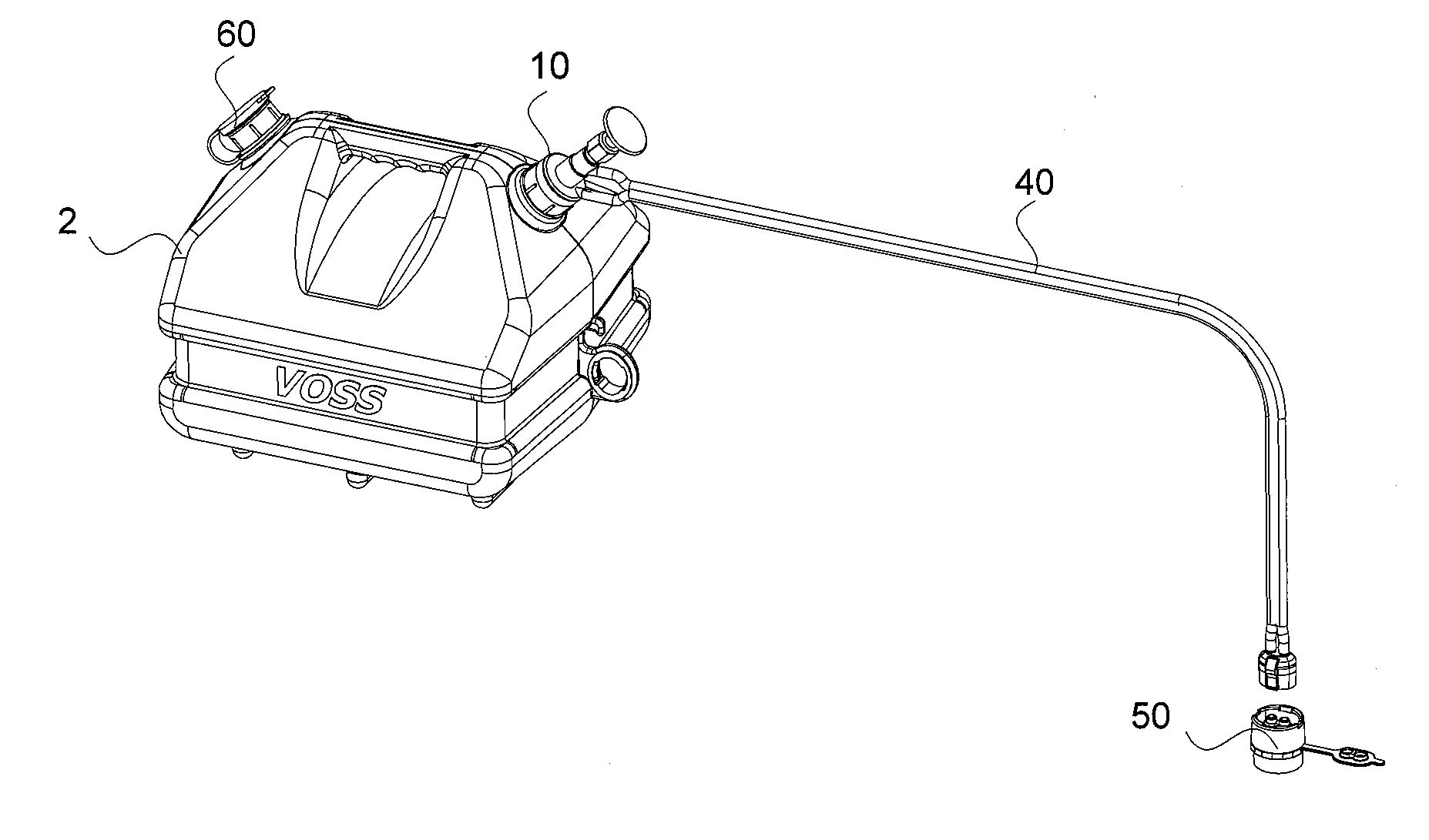
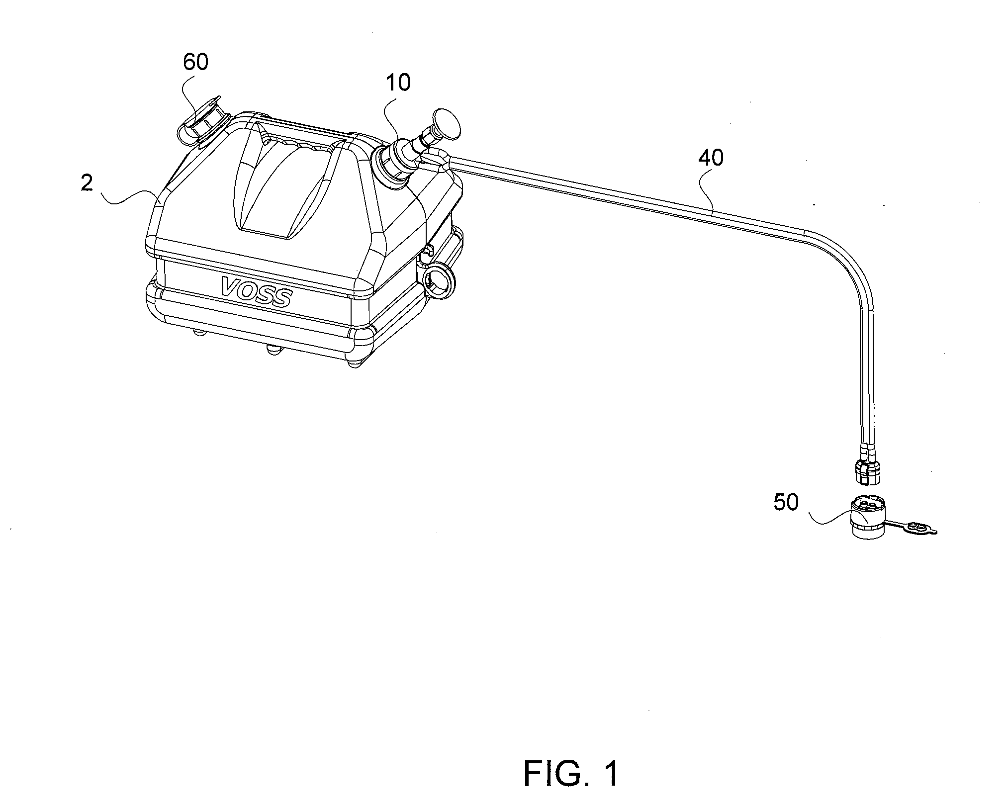
[0026]Referring to the Figures, various embodiments of an exemplary portable fuel dispensing system, and components thereof, are shown. A fuel dispensing system according to principles of the invention permits transfer of fuel from a portable fuel container, such as a gasoline canister, to an external fuel tank, such as the fuel tank of a portable motorized machine, in a sealed manner which prevents escape and spillage of vapors and liquid fuel. The embodiments disclosed herein are meant for illustration and not limitation of the invention. An ordinary practitioner will understand that it is possible to create other variations of the following embodiments without undue experimentation.

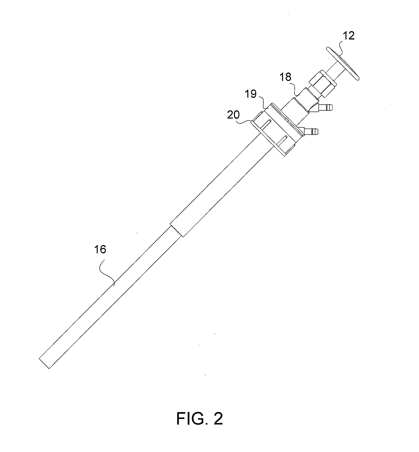
[0027]Referring to FIG. 1, the portable fuel dispensing system comprises a fuel pump assembly 10, a conduit 40, and a fuel tank cap assembly 50. In FIGS. 2 and 3, the pump assembly 10 comprises a handle assembly 11, a cylinder assembly 16, and pump body assembly. The pump handle assembly 11 comprises a...


PUM

PropertyMeasurementUnit
Pressureaaaaaaaaaa
Sizeaaaaaaaaaa
Flexibilityaaaaaaaaaa

Abstract

A portable fuel dispensing system comprises a fuel pump assembly, a conduit, and a fuel tank cap assembly. The pump assembly comprises a handle assembly, a cylinder assembly, and pump body assembly, and the conduit is a flexible hose or tube capable of channeling fuel from the pump assembly to the external fuel tank. The conduit and the fuel tank cap assembly comprises mating couplers having valves biased closed when disconnected from the mating coupler. In use, the fuel tank cap assembly is threaded to the external fuel tank, and the conduit coupler is connected to the cap coupler, thus forming a fluid-tight connection between the conduit and the fuel tank cap assembly. Thereafter, the external fuel tank may be replenished by manipulating the pump assembly. In other embodiments, the portable fuel dispensing system has a dual line conduit permitting vapor in the external fuel tank to be evacuated via a vapor line in the conduit and collected in the reservoir of the portable fuel container. In another embodiment, the pump assembly further comprises release valves disposed in the pump body assembly to alleviate pressure differences between the reservoir of the portable fuel container and the external ambient pressure.

Description

[0001]This application is a continuation-in-part of U.S. patent application Ser. No. 11 / 675,624, filed on Feb. 15, 2007, and a continuation-in-part of U.S. patent application Ser. No. 12 / 765,280, filed on Apr. 28, 2010.FIELD OF THE INVENTION[0002]This invention relates to portable fuel dispensing devices, and, more particularly, to a vented, non-spill fuel dispensing system with a releasable coupling for filling a fuel tank, and a vapour retention means to capture and retain fuel vapours emitted during the fueling process.BACKGROUND[0003]A common problem with filling fuel tanks is that fuel can easily spill out, especially where fuel is being poured from a portable fuel container through a nozzle into the fuel tank of a portable, motorized machine, such as a chain saw, weed eater, hedge trimmer, blower, lawn mower, or the like. As fuel flows into the machine's tank, the fuel can splash out of the tank or overfill the tank, causing fuel to spill onto surrounding objects. This spillag...

Claims


Application Information

Patent Timeline
IPC IPC(8): B65B31/04B67D7/58B65D51/16
CPCB60K2015/03217B60K15/0406
Inventor VOSS, III, FREDERICK
Owner VOSS INTPROP
Why Eureka
Try Eureka