Fuel cell system

Inactive Publication Date: 2010-09-23
TOYOTA JIDOSHA KK
View PDF2 Cites 11 Cited by
  • Summary
  • Abstract
  • Description
  • Claims
  • Application Information

AI Technical Summary

Benefits of technology

[0005]The present invention is made to solve such problems, and aims to improve starting performance of the fuel cell stack at low temperature.
[0007]Where the moisture content of the fuel cell stack is equal to or less than the predetermined threshold value, the reactive gas whose pressure is higher than the normal operating pressure is supplied to the fuel cell stack, thus achieving improvement of the starting performance of the fuel cell stack at low temperature while suppressing flooding.
[0009]When the electric power generation request electric current with respect to the fuel cell stack is more than the maximum electric current capable of being outputted by the fuel cell stack, the reactive gas whose pressure is higher than the normal operating pressure is supplied to the fuel cell stack, thus achieving improvement of maximum output characteristic of the fuel cell stack.
[0011]The applicant of the invention has confirmed through experiment that the output characteristic of the fuel cell stack is greatly improved where the fuel cell stack is supplied with the reactive gas whose pressure is made higher, compared with the normal operating pressure, as the moisture content of the fuel cell stack becomes less.

Problems solved by technology

In a state where moisture sufficient for ensuring a proton conductivity needed for power generation is contained in the film-electrode joined body when starting the fuel cell at low temperature, a raise in the supply pressure of the reactive gas causes flooding, and may deteriorate output characteristic of the fuel cell stack due to increase in concentration polarization caused by deterioration of the diffusion performance of the reactive gas.

Method used


Image

  • Fuel cell system
  • Fuel cell system
  • Fuel cell system

Examples


Embodiment Construction

[0018]The embodiment of the present invention is hereinafter described with reference to each figure.

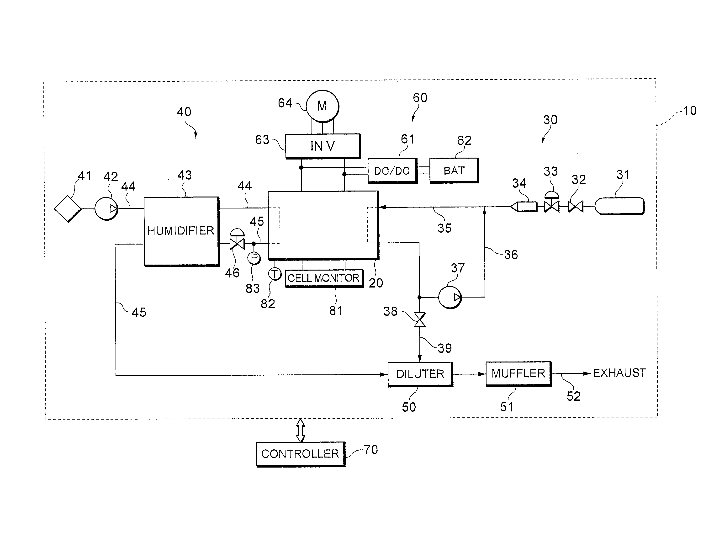
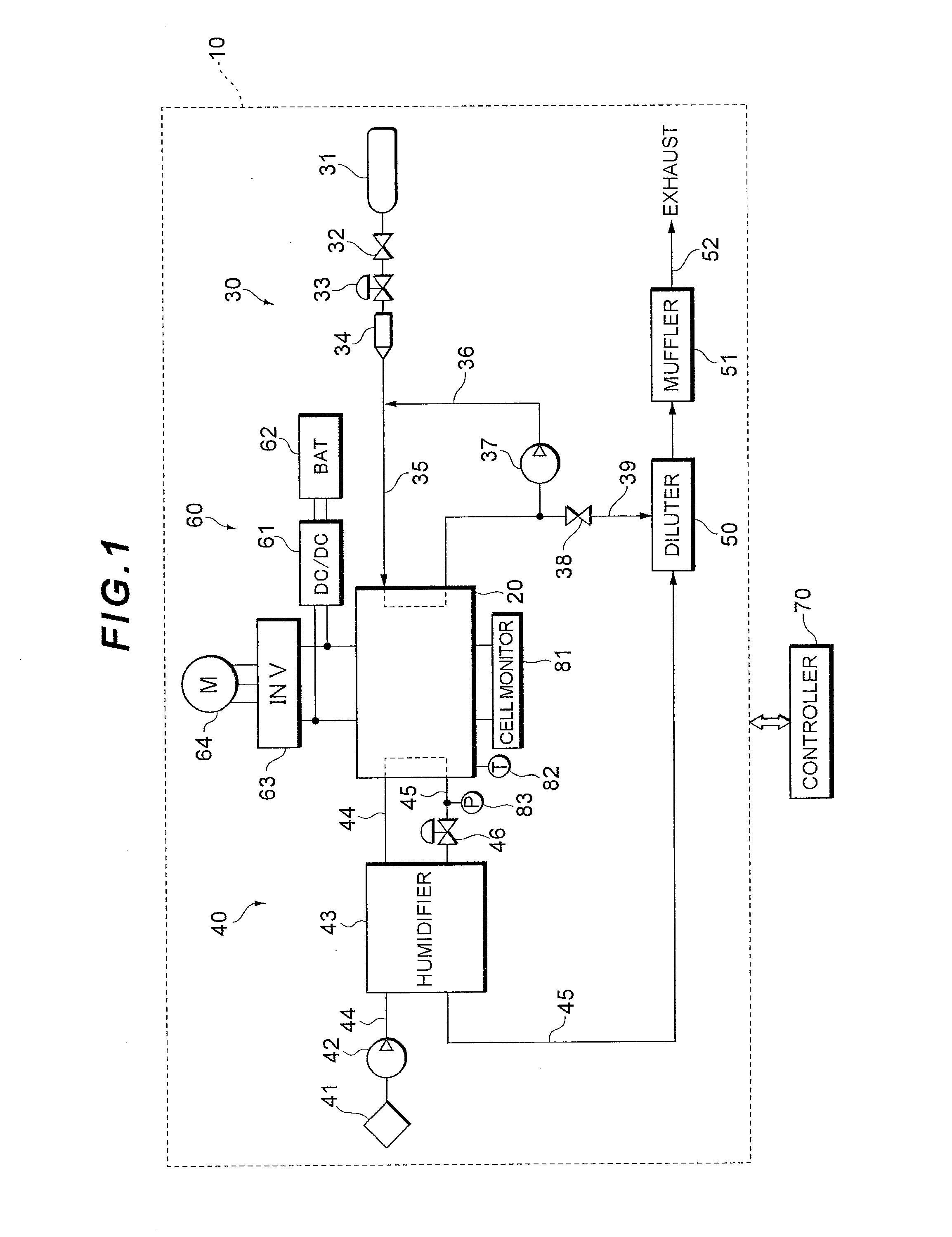
[0019]FIG. 1 shows a system configuration of a fuel cell system 10 functioning as a car-mounted electric power source system for a fuel cell vehicle.

[0020]The fuel cell system 10 has a fuel cell stack 20 generating electricity with a reactive gas (an oxidation gas and a fuel gas) supplied thereto, a fuel gas piping system 30 supplying a hydrogen gas as the fuel gas to the fuel cell stack 20, an oxidation gas piping system 40 supplying air as the oxidation gas to the fuel cell stack 20, an electric power system 60 controlling charging and discharging of electric power, and a controller 70 integrally controls the entire system.

[0021]The fuel cell stack 20 is, for example, a solid polymer electrolyte cell stack formed by stacking many cells in series. A cell has a cathode electrode on one side of an electrolyte film made of an ion exchange film, an anode electrode on the other side ther...


PUM


Abstract

A fuel cell system has a fuel cell stack generating electricity with a reactive gas supplied thereto and a controller supplying to the fuel cell stack the reactive gas whose pressure is higher than a normal operational pressure on condition that a temperature of the fuel cell stack is equal to or less than a predetermined threshold temperature and that a moisture content of the fuel cell stack is equal to or less than a predetermined threshold value. Where a supply pressure of the reactive gas is raised, an amount of moisture taken away by the reactive gas becomes less, and thus, water balance within the fuel cell stack shifts toward accumulation of moisture contained in the reactive gas into the film-electrode joined body. However, since the moisture content of the fuel cell stack is equal to or less than the predetermined threshold value, the system can improve the starting performance of the fuel cell stack at low temperature while suppressing flooding.

Description

TECHNICAL FIELD[0001]This invention relates to a fuel cell system having a fuel cell stack generating electricity with a reactive gas supplied thereto.BACKGROUND ART[0002]A fuel cell stack has a stack structure formed by stacking multiple cells in series, and each of the cells has film-electrode joined body formed by arranging an anode electrode on one side of an electrolyte film and a cathode electrode on the other side thereof. By supplying a reactive gas to the film-electrode joined body, an electrochemical reaction proceeds to convert chemical energy into electrical energy. Especially, a solid polymer electrolyte fuel cell stack using a solid polymer film as an electrolyte can be made smaller at low cost and has a high power density, and therefore the stack is expected to be used as a car-mounted electric power source.[0003]Since a cell reaction of the fuel cell system generates moisture, there exists a possibility that the moisture might freeze on an electrode catalyst, a gas d...

Claims


Application Information

Patent Timeline
IPC IPC(8): H01M8/04
CPCH01M8/04223H01M8/04291H01M8/0432H01M8/04365H01M8/0438Y02E60/50H01M8/04492H01M8/04552H01M8/04753H01M8/0488H01M8/0491H01M8/0441H01M8/04225H01M8/04302H01M8/04
Inventor KAJIWARA, SHIGETONONOBE, YASUHIROASO, SHINJI
Owner TOYOTA JIDOSHA KK
Why Eureka
Try Eureka