
EMI shielded conduit assembly for an active implantable medical device

Inactive Publication Date: 2010-09-23
WILSON GREATBATCH LTD
View PDF99 Cites 55 Cited by
  • Summary
  • Abstract
  • Description
  • Claims
  • Application Information

AI Technical Summary

Benefits of technology

[0032]The electronic circuit board, substrate or network preferably includes a low pass EMI filter, an L-C trap, a bandstop filter, a programmable short-to-housing switch network, or a combination thereof. The low pass EMI filter may include a capacitor, a feedthrough capacitor, an MLCC chip capacitor, a flat-through capacitor, an X2Y attenuator, a multi-element low-pass filter, an active electronic filter, or a combination thereof. The low pass EMI filter and the L-C trap may be grounded to the EMI shield. Moreover, the low pass filter, the L-C trap, or the bandstop filter may be disposed on the circuit board or the substrate. Preferably, the EMI shield extends from the hermetic feedthrough term

Problems solved by technology

Such EMI signals may interfere with the proper operation of AIMD electronic circuits.
It has been shown in the past that such re-radiation can cause AIMD internal electronic circuit malfunction.
When the high frequency EMI energy is diverted to the AIMD electromagnetic shield housing 104, it simply circulates as eddy currents resulting in a few milliwatts of insignificant power dissipation as a small amount of heat.
This results in a miniscule and insignificant temperature rise of the AIMD electromagnetic shield housing 104.
Although, the filters did their job and acted as a low impedance, they tended to pull stray EMI RF currents from the outside world to the point of filtering.
There are a number of problems associated with low pass EMI feedthrough filters mounted directly to the hermetic terminal 100, including increased cost, masking a hermetic seal leaker, and reduced reliability.
Cost is increased because it is difficult to reliably mount the filter elements (such as a multipin feedthrough capacitor) on or immediately adjacent to the hermetic terminal subassembly.
However, when the filter is mounted directly to or against the hermetic terminal subassembly, it is subjected to significant installation stresses.
Installation of these filter elements to the hermetic seal typically involves expensive silver-filled thermal-setting conductive flexible adhesives such as polyimides.
In addition to being expensive, these materials are difficult to dispose into the correct positions and require carefully fixturing and cleaning operations.
An additional cost comes from the fact that these life-saving devices go through high reliability screening.
Failure of the electronic filter means that the entire hermetic seal subassembly is also scrap.
This is an expensive proposition due to the fact that hermetic terminal subassembly is typically manufactured with biocompatible materials including platinum, platinum iridium pins, gold brazes and the like.
In other words, a significant amount of the cost of this subassembly is due to the precious metals involved in its design.
Therefore, a significant problem in the prior art relates to the mounting of feedthrough or MLCC capacitors and other types of EMI filters on or adjacent to a hermetic terminal pin / seal subassembly.
However, these channels / paths are difficult to manufacture and also add cost.
These devices tend to be more sensitive to EMI than passive pumps that have no sense circuitry or externally implanted leadwires.
Cell phones, microwave ovens and the like have all been implicated in causing interference with active implantable medical devices.
At very high frequencies, such as above 1 GHz, this problem becomes quite serious.
Monolithic ceramic manufacturing limitations on electrode thickness and conductivity means that the prior art flat-through capacitors 190 have relatively high series resistance and can only be rated to a few hundred milliamps or a few amps at best (however, an implantable defibrillator must deliver a high voltage pulse of over 20-amps).
However, because of this cross-coupling, there is always going to be a certain frequency at which the attenuation starts to parasitically drop off as shown.
This drop off is very undesirable in active implantable medical device (AIMD) applications in that there would be less protection against high frequency EMI emitters such as cellular phones and the like.
This parasitic drop off in attenuation due to cross-coupling is even a worse problem in military and space applications where EMI filter attenuation requirements of up to 10 or even 18 GHz, is important (implantable medical applications do not generally require filtering much above 3 GHz due to the effective reflection and absorption of human skin of RF energy at frequencies above 3 GHz).

Method used


Image

  • EMI shielded conduit assembly for an active implantable medical device
  • EMI shielded conduit assembly for an active implantable medical device
  • EMI shielded conduit assembly for an active implantable medical device

Examples


Embodiment Construction

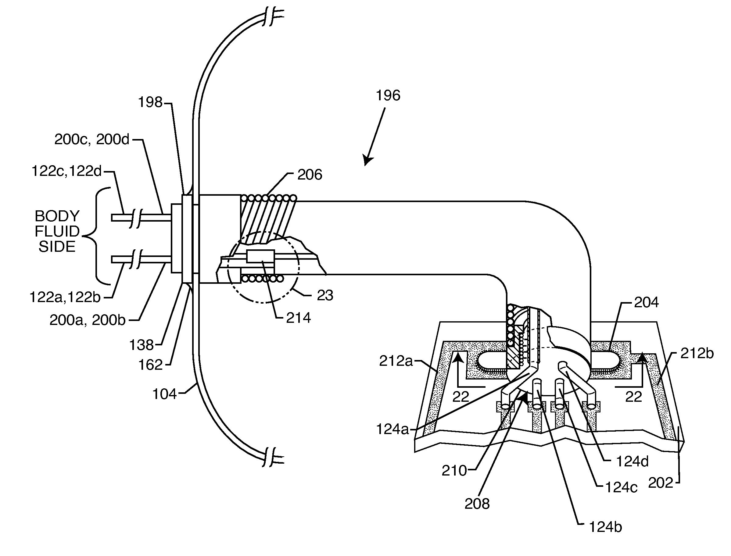
[0116]In accordance with the present invention, the EMI shielded conduit assembly for an active implantable medical device (AIMD) comprises: (1) an EMI shielded housing for the AIMD; (2) a hermetic feedthrough terminal associated with the AIMD housing; (3) an electronic circuit board, substrate or network disposed within the AIMD housing remote from the hermetic feedthrough terminal; (4) at least one leadwire extending from the hermetic feedthrough terminal to the remote electronic circuit board, substrate or network; and (5) an EMI shield conductively coupled to the AIMD housing and co-extensively extending about the at least one leadwire in non-conductive relation. In the following detailed description, functionally equivalent components of various embodiments will be referred to by the same reference numbers or letters.

[0117]Accordingly, by removing the filter capacitor or low pass filter or other components from the hermetic seal to a remote location, one can test the hermetic s...


PUM


Abstract

An EMI shielded conduit assembly for an active implantable medical device (AIMD) includes an EMI shielded housing for the AIMD, a hermetic feedthrough terminal associated with the AIMD housing, and an electronic circuit board, substrate or network disposed within the AIMD housing remote from the hermetic feedthrough terminal. At least one leadwire extends from the hermetic feedthrough terminal to the remote circuit board, substrate or network. An EMI shield is conductively coupled to the AIMD housing and substantially co-extends about the leadwire in non-conductive relation thereto.

Description

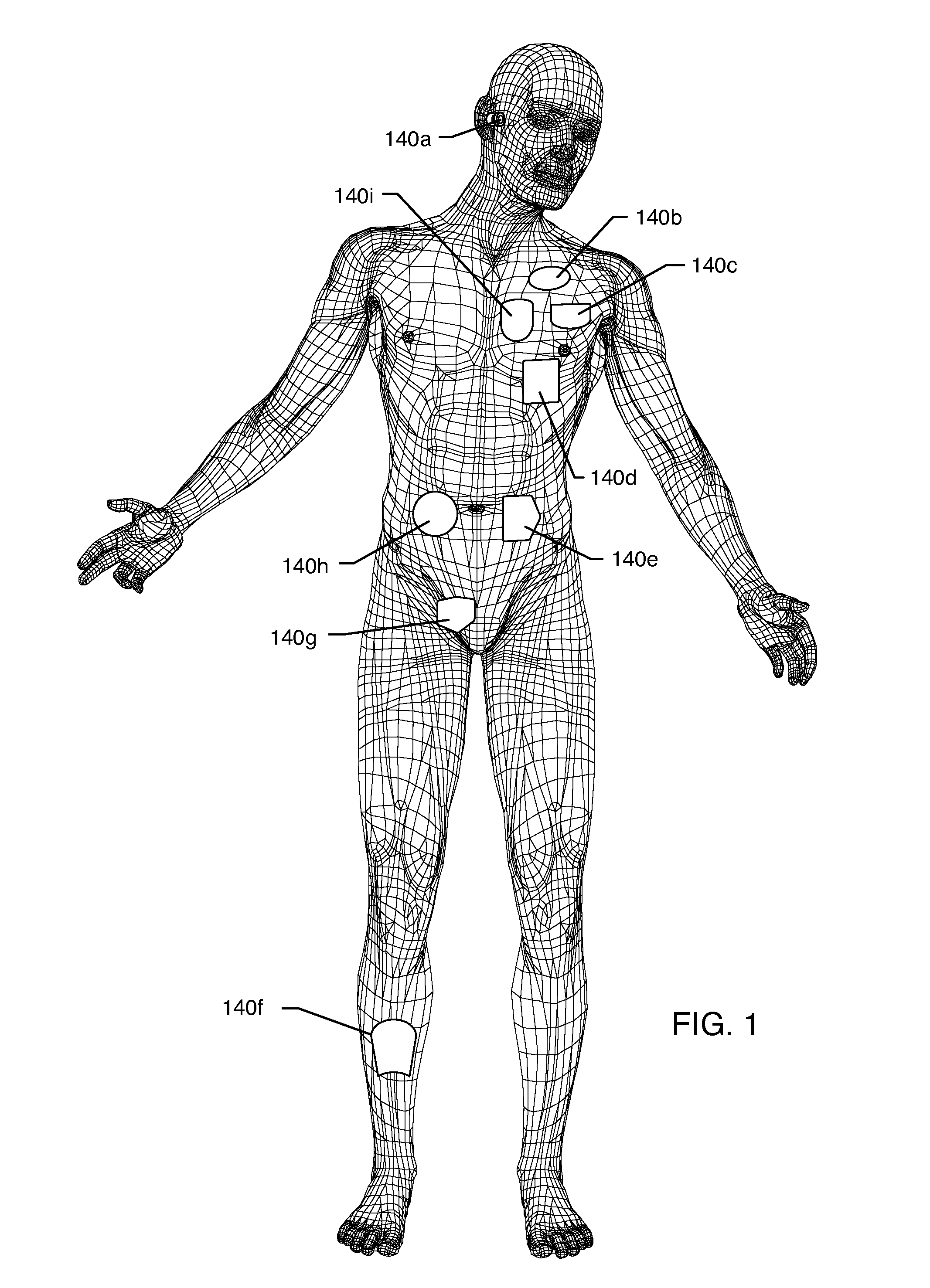
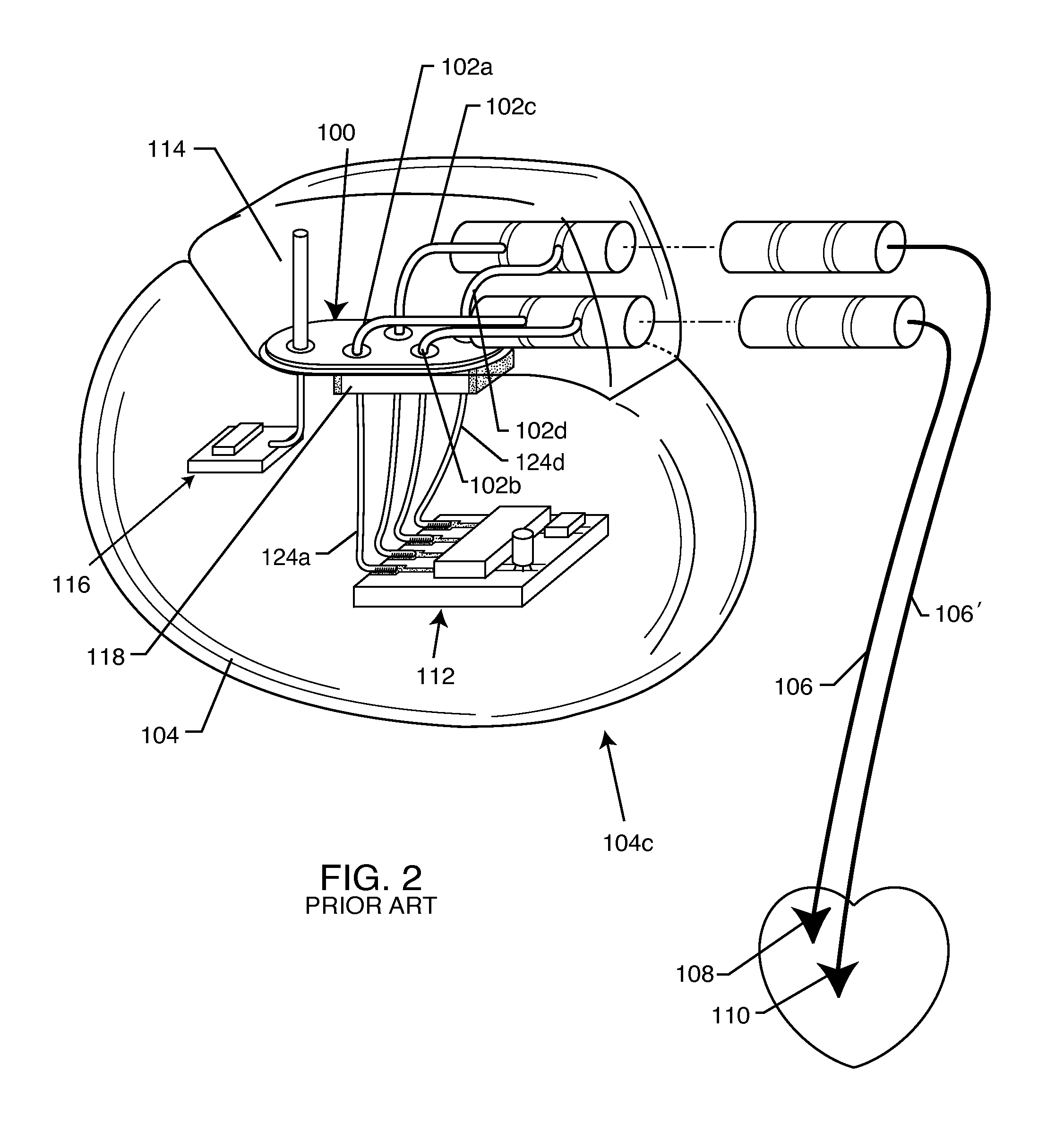
BACKGROUND OF THE INVENTION[0001]The present invention generally relates to active implantable medical devices (AIMDs). More particularly, the present invention relates to an EMI shielded conduit for leads extending from the hermetic feedthrough terminal of an active implantable medical device to a remote electronic circuit board, substrate or network located within the AIMD hermetically sealed and electromagnetically shielded housing.[0002]Feedthrough hermetic terminals are generally well-known in the art for connecting electrical signals through the housing or case of an AIMD such as those illustrated in FIG. 1. For example, in implantable medical devices such as cardiac pacemakers, shown in FIG. 2, implantable cardioverter defibrillators, and the like, a hermetic terminal 100 comprises one or more conductive terminal pins 102a-102d supported by an insulative structure for feedthrough passage from the exterior to the interior of an AIMD electromagnetic shield housing 104. Many dif...

Claims


Application Information

Patent Timeline
IPC IPC(8): A61N1/00
CPCA61B5/0031A61B5/042A61B2018/00839A61B2019/5236A61B2562/182A61B5/7203A61B2562/227A61N1/3718A61N2001/086G01R33/285A61B2562/222A61B2090/374A61N1/086A61B5/283
Inventor TRUEX, BUEHL E.STEVENSON, ROBERT A.BRENDEL, RICHARD L.
Owner WILSON GREATBATCH LTD
Features
  • Generate Ideas
  • Intellectual Property
  • Life Sciences
  • Materials
  • Tech Scout
  • Unparalleled Data Quality
  • Higher Quality Content
  • 60% Fewer Hallucinations
Learn More