Thermal conductivity sensor

a technology of conductivity sensor and thermal conductivity, which is applied in the direction of instruments, chemical methods analysis, separation processes, etc., can solve the problems of increasing costs, aggravating the signal-to-noise ratio, and difficulty in obtaining correct measurement, so as to reduce the production errors of the enclosure, the effect of improving the sensitivity of measuremen

Inactive Publication Date: 2010-09-30
HORIBA LTD
View PDF5 Cites 16 Cited by
  • Summary
  • Abstract
  • Description
  • Claims
  • Application Information

AI Technical Summary

Benefits of technology

[0014]According to the present invention constructed in this manner, the measurement sensitivity can be improved by enlarging the detection sign

Problems solved by technology

However, since the disposal temperature and the temperature coefficient are different between the external resistors, and the measurement resistor and the reference resistor, the temperature influence received from the outside is different between the external resistors, and the measurement resistor and the reference resistor, thereby making it difficult to obtain correct measurement results.
However, the temperature influence that the external resistors receive may be different product by product due to the variation in the temperature coefficient of the external resistors, so that a correction coefficient of the temperature correction circuit must be set product by product, and the setting thereof is cumbersome, thereby causing an increase in costs.
Further, by electric signals from

Method used


Image

  • Thermal conductivity sensor
  • Thermal conductivity sensor
  • Thermal conductivity sensor

Examples


Embodiment Construction

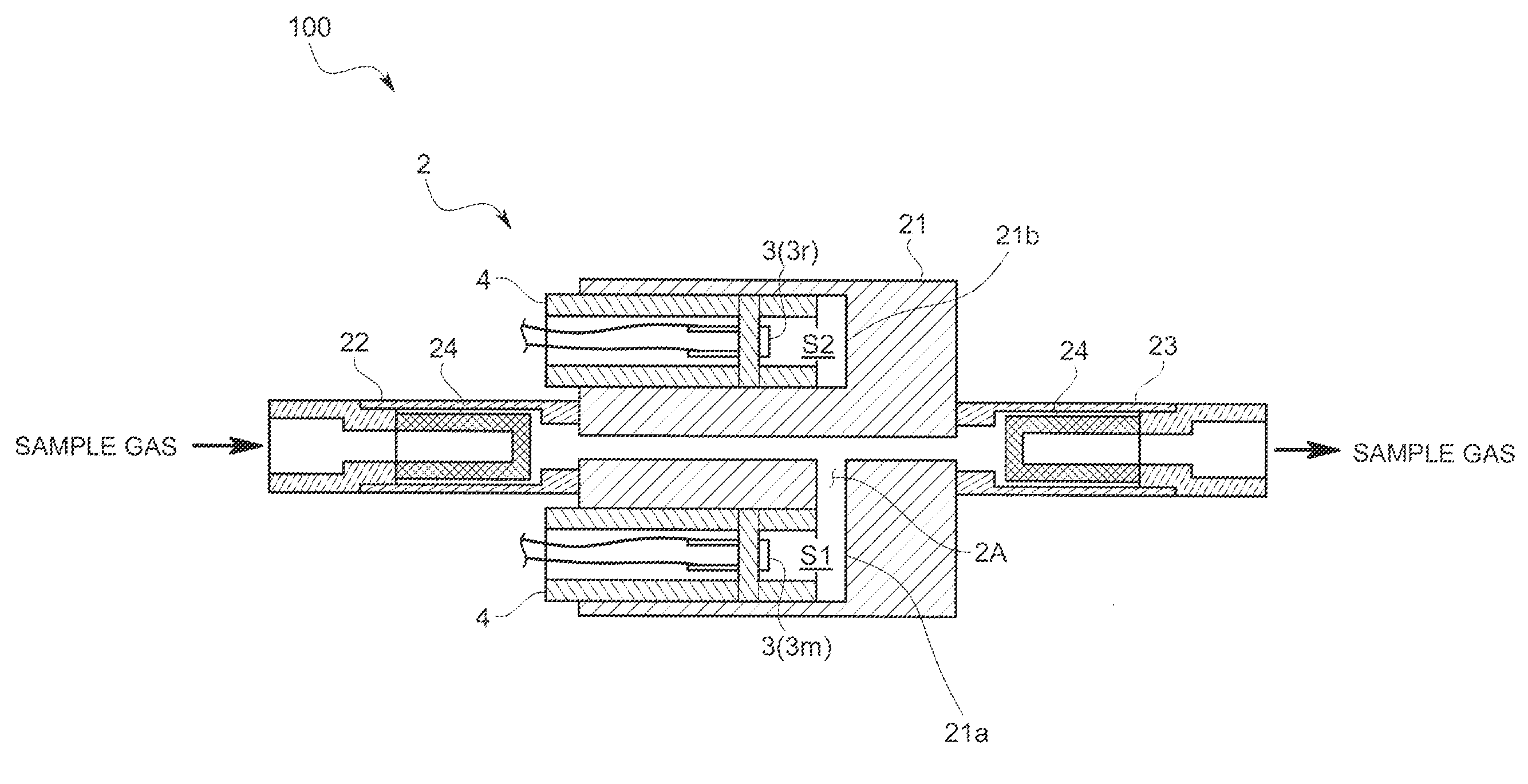
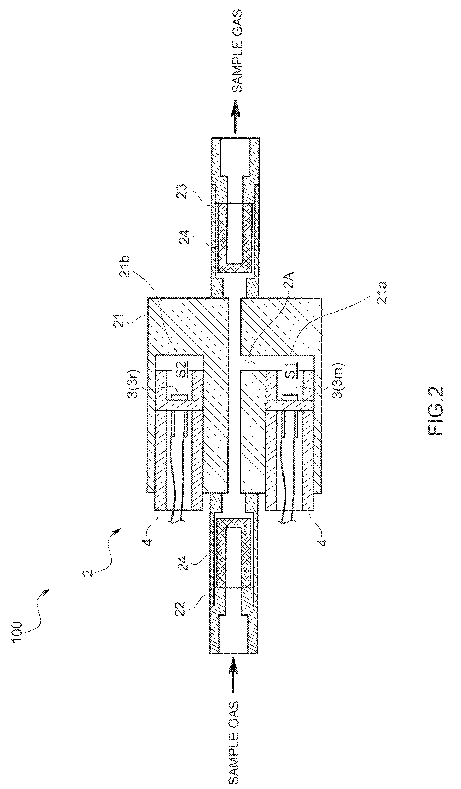
[0021]Hereafter, one embodiment of a thermal conductivity sensor according to the present invention will be described with reference to the drawings.

[0022]A thermal conductivity sensor 100 according to the present embodiment detects the thermal conductivity of a sample gas containing a combustible and / or corrosive component and measures the concentration of a predetermined component in the sample gas based on the thermal conductivity. Here, the combustible and / or corrosive component may be, for example, water (H2O), an oxygen (O2) gas, a sulfur oxide (SOX) gas, a nitrogen oxide (NOX) gas, a hydrochloric acid (HCl) gas, an ammonia (NH3) gas, a hydrogen sulfide (H2S gas, or a hydrogen (H2) gas.

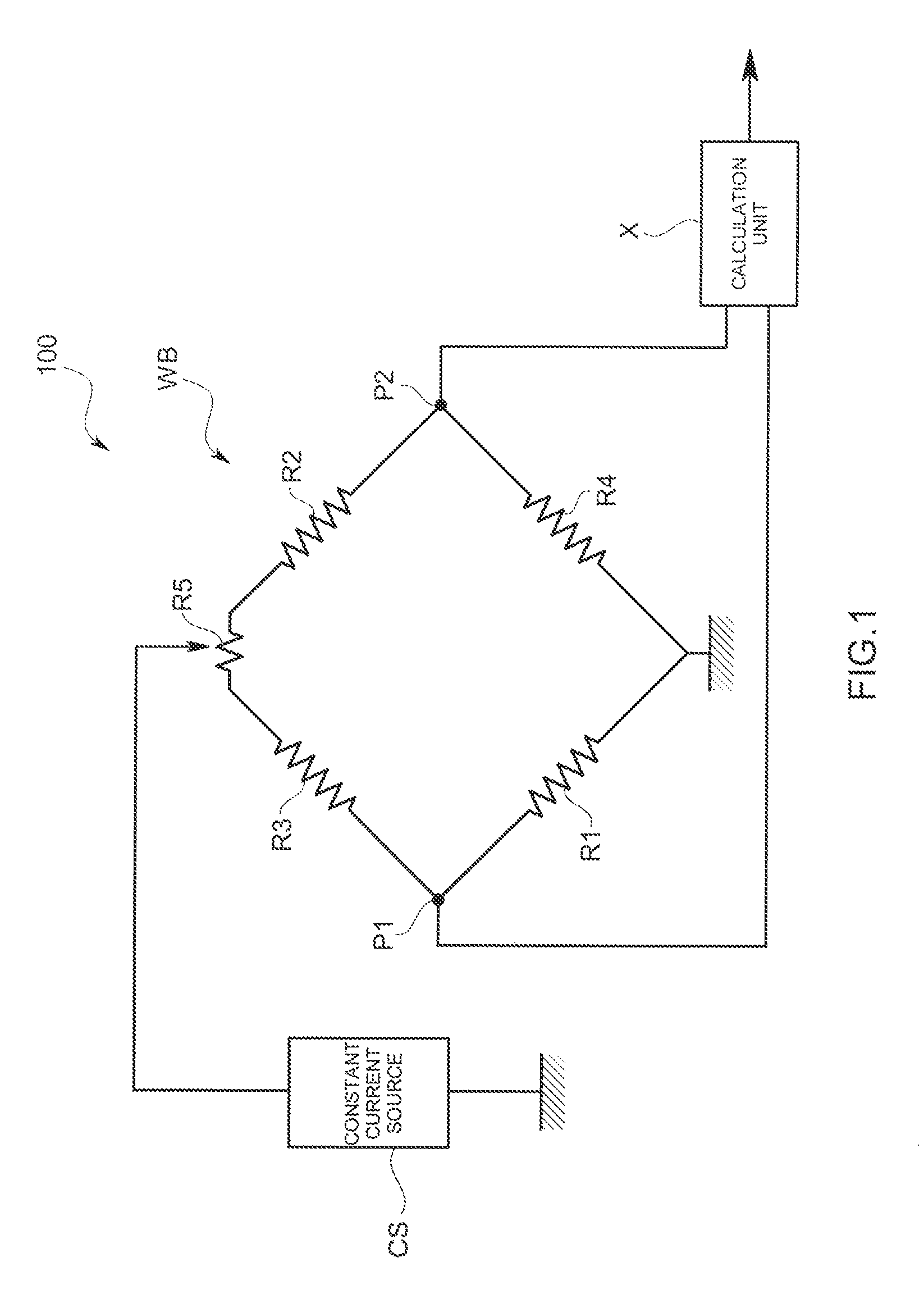
[0023]First, a measurement circuit of the thermal conductivity sensor 100 will be described with reference to FIG. 1.

[0024]This measurement circuit is constructed with two measurement resistors R1 and R2 that are disposed to be in contact with a sample gas and two reference resistors R3 and R4 t...


PUM


Abstract

The measurement sensitivity is improved by suppressing the surrounding temperature influence as much as possible, while realizing scale reduction, and by enlarging the detection signal, while reducing the production errors in enclosing a reference gas. Provided is a thermal conductivity sensor that detects thermal conductivity of a sample gas by using a Wheatstone Bridge circuit constructed in such a manner that measurement resistors that are brought into contact with the sample gas are disposed on a first side, and reference resistors that are brought into contact with a reference gas are disposed on a second side, and comparing the potential difference between connection points of the reference resistors and the measurement resistors. The measurement resistors disposed on the first side are assembled in one measurement space, and the reference resistors disposed on the second side are assembled in one reference space.

Description

BACKGROUND OF THE INVENTION[0001]1. Field of the Invention[0002]The present invention relates to a thermal conductivity sensor that detects the thermal conductivity of a sample gas by using a Wheatstone Bridge circuit and measures the concentration of a predetermined component in the sample gas based on the thermal conductivity.[0003]2. Description of the Related Art[0004]Conventionally, a thermal conductivity sensor of this kind is constructed in such a manner that one measurement resistor is assembled in a measurement cell; one reference resistor is assembled in a reference cell; and other resistors are disposed outside of the cells as external resistors, constituting a Wheatstone Bridge circuit, as described in Japanese Patent Application Laid-open (JP-A) No. 2003-42983.[0005]However, since the disposal temperature and the temperature coefficient are different between the external resistors, and the measurement resistor and the reference resistor, the temperature influence receiv...

Claims


Application Information

Patent Timeline
IPC IPC(8): G01N25/18
CPCG01N25/18G01N30/66
Inventor MATSUHAMA, MAKOTOSEKO, TOMOKOTAKADA, SHUJIMIZUTANI, HIROSHIOIDA, TAKUJIENDO, MASAHIKOIDO, TAKUYA
Owner HORIBA LTD
Why Eureka
Try Eureka