
Light emitting device comprising a green emitting sialon-based material

a technology of green emitting sialon and light-emitting device, which is applied in the direction of discharge tube luminescent screen, discharge tube/lamp details, luminescent composition, etc., can solve the problems of complex lack of color point saturation, spectrum which is too broad, and many applications are too broad, so as to improve optical features and improve production. stability and the effect of good stability

Active Publication Date: 2010-09-30
LUMILEDS
View PDF8 Cites 14 Cited by
  • Summary
  • Abstract
  • Description
  • Claims
  • Application Information

AI Technical Summary

Benefits of technology

[0008]It is an object of the present invention to provide a light emitting device with a material which has improved optical features together with a good producibility and stability
[0014]Such a material has shown for a wide range of applications within the present invention to have at least one of the following advantages:
[0015]The stability of the material is usually improved comprising to materials of the prior art. The material has usually a very high thermal, especially photothermal stability.
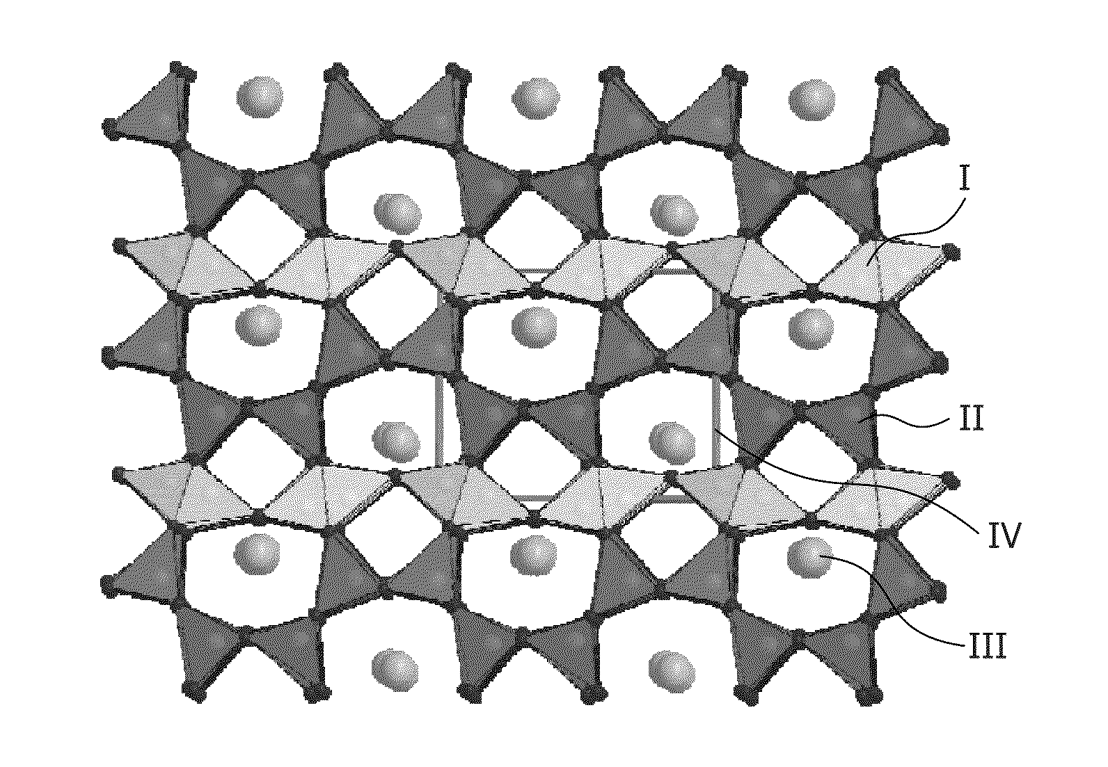
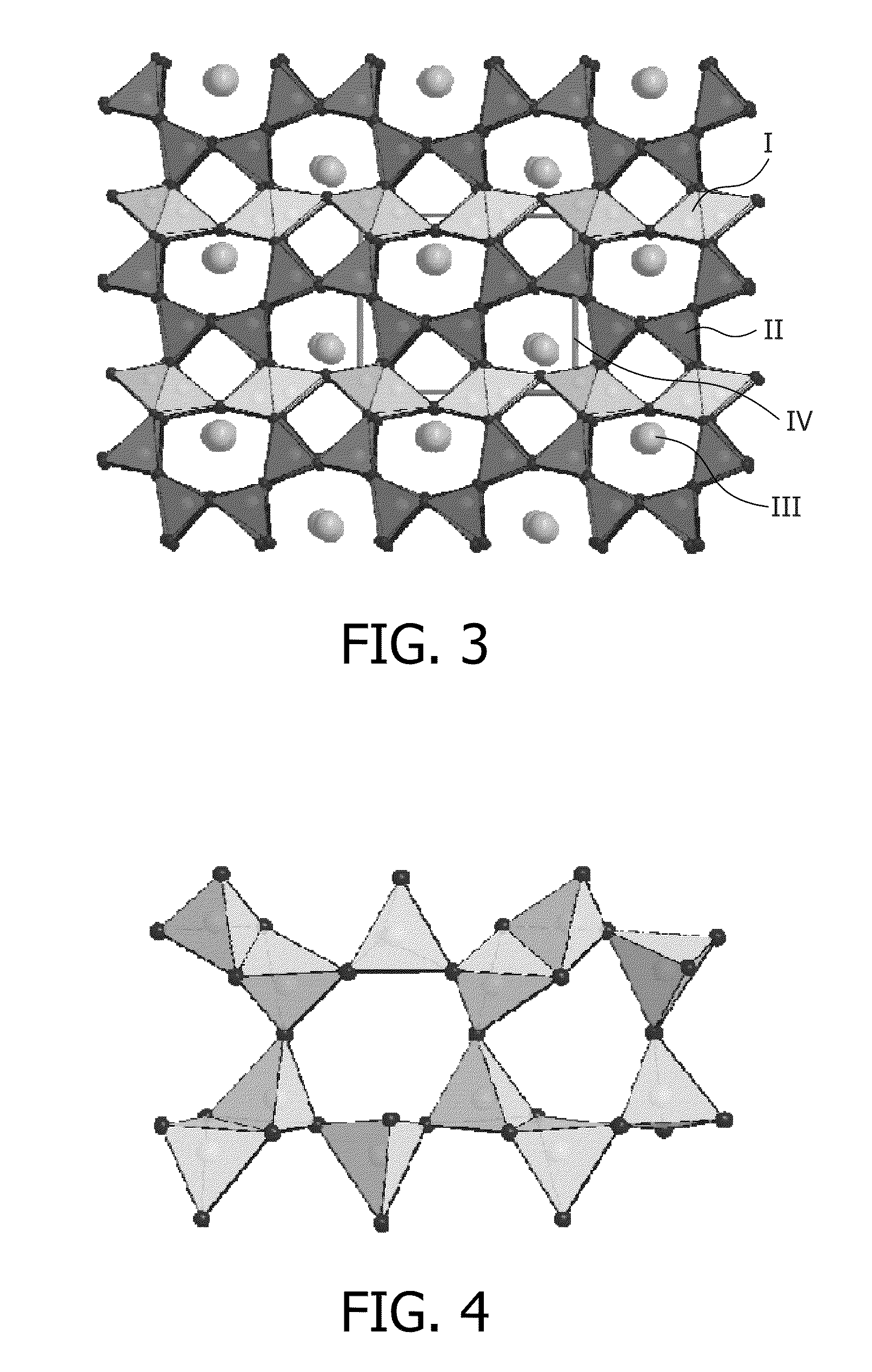
[0028]According to a preferred embodiment of the present invention, the green emitting material has a orthorhombic crystal structure. It has been found for many applications within the present invention that by doing so, the properties (especially the emission profile) of the material may be further enhanced.
[0034]According to a preferred embodiment of the present invention, the photothermal stability of the ceramic material is ≧80% to ≦100% after exposure of the ceramic material for 1000 hrs at 200° C. with a light power density of 10 W / cm2 and an average photon energy of 2.75 eV.
[0036]According to a preferred embodiment of the present invention, the photothermal stability of the ceramic material is ≧82.5% to ≦95%, preferably ≧85% to ≦97%, after exposure of the ceramic material for 1000 hrs at 200° C. with a light power density of 10 W / cm2 and an average photon energy of 2.75 eV.

Problems solved by technology

However, this compound often lacks saturation of the color point and has for some applications a spectrum which is too broad.
However, here the spectrum is too broad for many applications and it has been shown that this compound has somewhat a tendency to degenerate in moist air.

Method used


Image

  • Light emitting device comprising a green emitting sialon-based material
  • Light emitting device comprising a green emitting sialon-based material
  • Light emitting device comprising a green emitting sialon-based material

Examples


example i

[0072]The invention will be better understood together with the Example I which—in a mere illustrative fashion—is one Example of a inventive green emitting material.

[0073]Example I refers to Sr4.9Al5Si21O2N35:Eu0.1 which was made the following way: 16.4 g AlN (98.5%), 35.14 g SrH2 (98.5%), 1.41 g Eu2O3 (99.99%), and 82.3 g SiNxOy (x=1.66, y=0.02) is mixed under inert atmosphere in a plastic box and fired at 1550° C. for two times with intermediate milling.

[0074]The resulting powder is washed with water and dried.

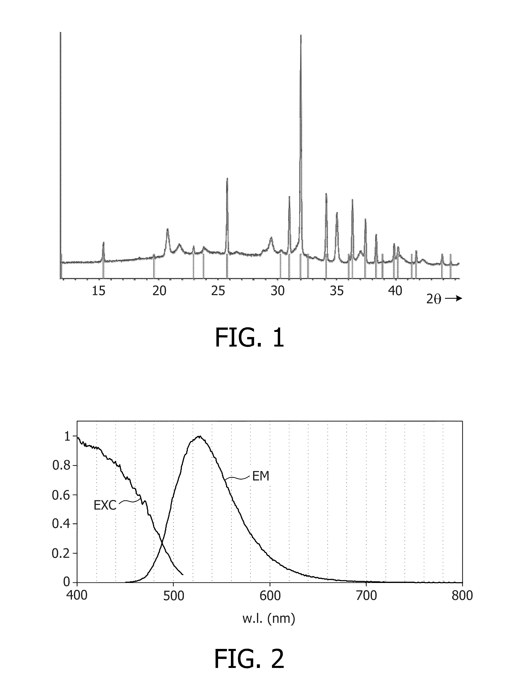
[0075]FIG. 1 shows the XRD pattern of the SiAlON phosphor that comprises sharp and diffuse reflections due to stacking disorder within the crystals. The degree of disorder can be influenced by dwell time and cooling rate of the firing profile. Surprisingly it was found out that a high degree of disorder of the layer stacking has no influence on the efficiency of the luminescent material. The sharp reflections (indicated by red lines) can be indexed with an orthorhombic sub c...


PUM

PropertyMeasurementUnit
half-widthaaaaaaaaaa
energyaaaaaaaaaa
crystal structureaaaaaaaaaa

Abstract

The invention relates to a light emitting device, especially a LED comprising a green emitting material of the composition Sr5−y−z−aMySi23−xAl3+xOx+2aN37−x−2a:Euz:Cez1. This material has been found to have a narrow emission in the green wavelight range together with a good producibility and stability.

Description

FIELD OF THE INVENTION[0001]The present invention is directed to light emitting devices, especially to the field of LEDs.BACKGROUND OF THE INVENTION[0002]Phosphors comprising silicates, phosphates (for example, apatite) and aluminates as host materials, with transition metals or rare earth metals added as activating materials to the host materials, are widely known. As blue LEDs, in particular, have become practical in recent years, the development of white light sources utilizing such blue LEDs in combination with such phosphor materials is being energetically pursued.[0003]Especially luminescent materials based on the so-called “SiAlON”-system have found the focus of attention in the field due to their good optical features.[0004]However, there is still the continuing need for luminescent materials which are usable within a wide range of applications and especially allow the fabrication of phosphor warm white pcLEDs with optimized luminous efficiency and color rendering.[0005]Espe...

Claims


Application Information

Patent Timeline
Patent Type & Authority Applications(United States)
IPC IPC(8): H01L33/44
CPCC09K11/0883C09K11/7734C04B35/597C04B35/6261C04B2235/3213C04B2235/9607C04B2235/3865C04B2235/3873C04B2235/761C04B2235/77C04B2235/3224C09K11/77348
Inventor SCHMIDT, PETER J.MAYR, WALTERMEYER, JOERGKECHELE, JULIANE ANGELIKASCHNICK, WOLFGANGOECKLER, OLIVER MICHAEL
Owner LUMILEDS
Learn More