Solid electrolytic capacitor

a solid electrolytic capacitor and capacitor technology, applied in the direction of electrolytic capacitors, capacitor electrodes, liquid electrolytic capacitors, etc., can solve the problems of insufficient reduction of stress transmitted from the ano insufficient reduction of stress applied from the anode terminal and insufficient reduction of stress applied through the anode lead to the dielectric layer. , to achieve the effect of suppressing transmission, suppressing transmission

Active Publication Date: 2010-09-30
SANYO ELECTRIC CO LTD
View PDF12 Cites 23 Cited by
  • Summary
  • Abstract
  • Description
  • Claims
  • Application Information

AI Technical Summary

Benefits of technology

[0054]In the solid electrolytic capacitor 20 according to this embodiment, the exposed portion 40, the other end 2b of the anode lead 2 and the connecting part α are covered with a resin layer 10 composed of first and second resin layers 10a and 10b. Since the other end 2b of the anode lead 2 is covered with the resin layer 10, it can be prevented that in the molding process the resin for forming the resin outer package 11 comes into direct contact with the other end 2b of the anode lead 2. Therefore, transmission of stress generated by a pouring pressure through the anode lead 2 to the dielectric layer 3 can be suppressed. In addition, even if the stress generated by a pouring pressure is transmitted to the anode terminal 7 having a large surface area, the resin layer 10 formed from around the other end 2b of the anode lead 2 to around the connecting part α can suppress transmission of the stress from the anode terminal 7 through the anode lead 2 to the dielectric layer 3. Therefore, in the solid electrolytic capacitor 20 according to this embodiment, the occurrence of cracks in the dielectric layer 3 can be suppressed, and the leakage current can thereby be reduced.
[0055]Furthermore, the first resin layer 10a of the solid electrolytic capacitor 20 according to this embodiment is softer than the second resin layer 10b thereof. Therefore, the first resin layer 10a can reduce stress applied to the exposed portion 40 of the electrolyte layer 4, and the second resin layer 10b can mechanically reinforce the first resin layer 10a to enhance the stress reduction effect of the first resin layer 10a on the exposed portion 40. As a result, the occurrence of cracks in the dielectric layer 3 can be suppressed, and the leakage current can thereby be reduced.
[0056]In addition, the connecting part α of the solid electrolytic capacitor 20 according to this embodiment is covered with the first resin layer 10a softer than the second resin layer 10b. Therefore, stress applied to the connecting part α in the molding process can be reduced, which further suppresses the stress transmitted from the anode terminal 7 through the anode lead 2 to the dielectric layer 3.
[0057]In this embodiment, after the connection between the anode lead 2 and the anode terminal 7 and before the formation of the resin outer package 11, the first resin layer 10a is formed on the exposed portion 40 and from around the other end 2b of the anode lead 2 to around the connecting part α, and the second resin layer 10b is formed to cover the first resin layer 10a. Therefore, the anode lead 2, the anode terminal 7 and the capacitor element 6 are rigidly held by the resin layer 10 prior to the molding process. Thus, the stress transmitted from the anode terminal 7 through the anode lead 2 to the dielectric layer 3 in the molding process can be reduced. Accordingly, the occurrence of cracks in the dielectric layer 3 can be suppressed, and the leakage current can thereby be reduced.
[0058](Modification 1 of First Embodiment)
[0059]Next will be described below a solid electrolytic capacitor 25 according to Modification 1 of the first embodiment. Note that the following description is made mainly of the formation of a third resin layer 13, which is a difference from the above described first embodiment.

Problems solved by technology

This results in insufficient reduction of stress transmitted from the anode lead to the dielectric layer.
If in such a case only the root of the anode lead is rigidly held by a thermosetting resin, the stress applied from the anode terminal through the anode lead to the dielectric layer cannot sufficiently be reduced.
Accordingly, the method described in the above document cannot sufficiently suppress the occurrence of cracks in a part of the dielectric layer located in the vicinity of the region in which the anode and the anode lead are joined together, and cannot thereby sufficiently reduce the leakage current.

Method used


Image

  • Solid electrolytic capacitor
  • Solid electrolytic capacitor
  • Solid electrolytic capacitor

Examples


first embodiment

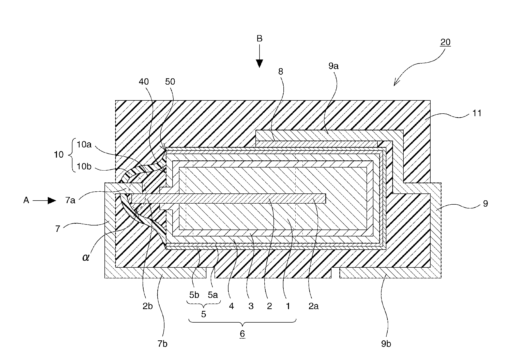
[0037]FIG. 1 is a schematic cross-sectional view for illustrating the interior of a solid electrolytic capacitor according to this embodiment.

[0038]A solid electrolytic capacitor 20 according to this embodiment has the outer shape of a rectangular box. The solid electrolytic capacitor 20, as shown in FIG. 1, basically includes a capacitor element 6, an anode terminal 7, a cathode terminal 9, a resin outer package 11, and a resin layer 10 composed of a first resin layer 10a and a second resin layer 10b. These elements will be described below in an orderly sequence.

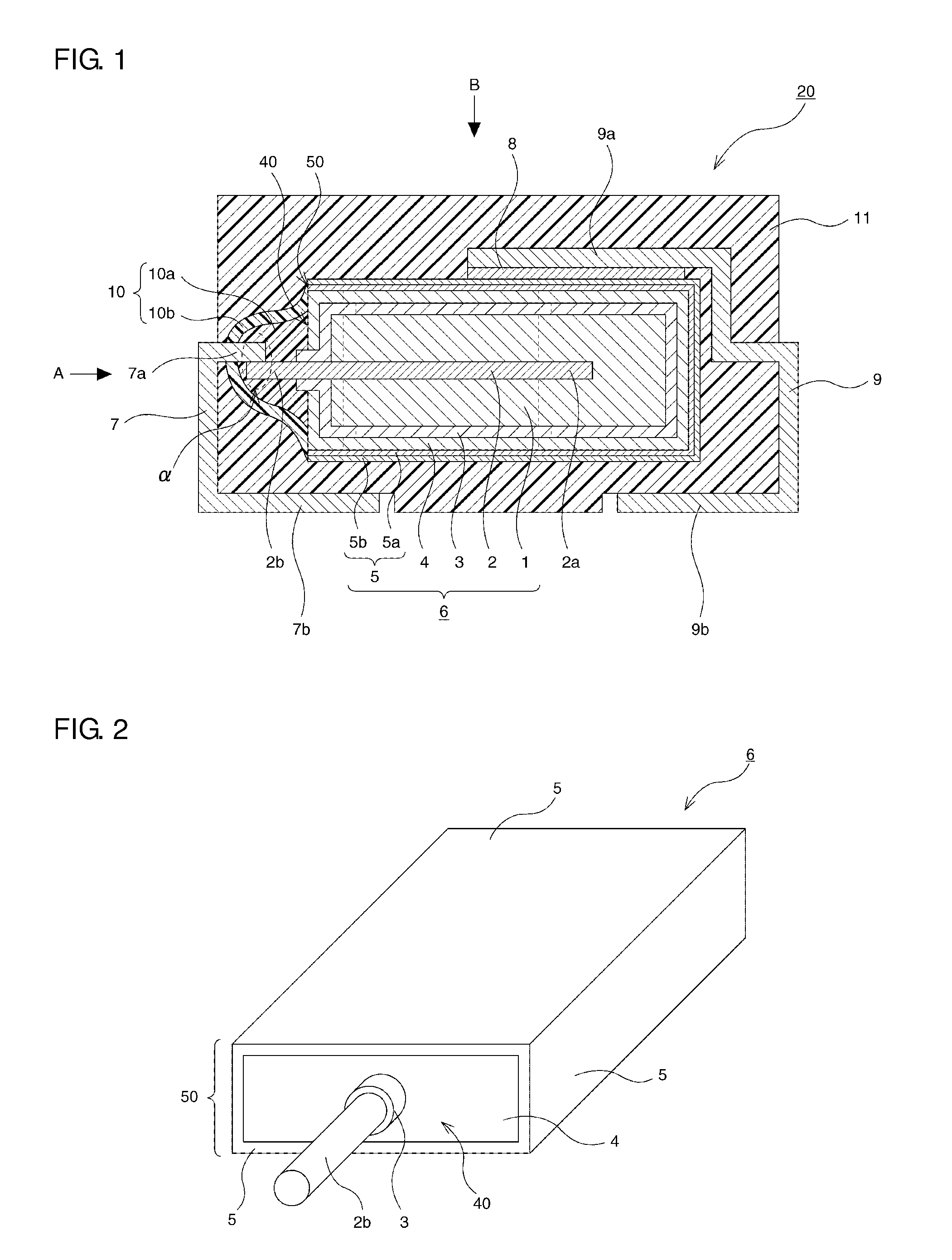
[0039]The capacitor element 6 includes an anode 1 made of a valve metal, an anode lead 2 provided so that its one end 2a is joined to the anode 1 and the other end 2b extends from the anode 1, a dielectric layer 3 formed by anodizing the anode 1, an electrolyte layer 4 covering the dielectric layer 3, and a cathode layer 5 covering the electrolyte layer 4.

[0040]The anode 1 is formed of a porous body made by pressing a large...

second embodiment

[0070]Next will be described below a solid electrolytic capacitor 21 according to a second embodiment. Note that the following description is made mainly of the formation of a resin layer 10, which is a difference from the above described first embodiment.

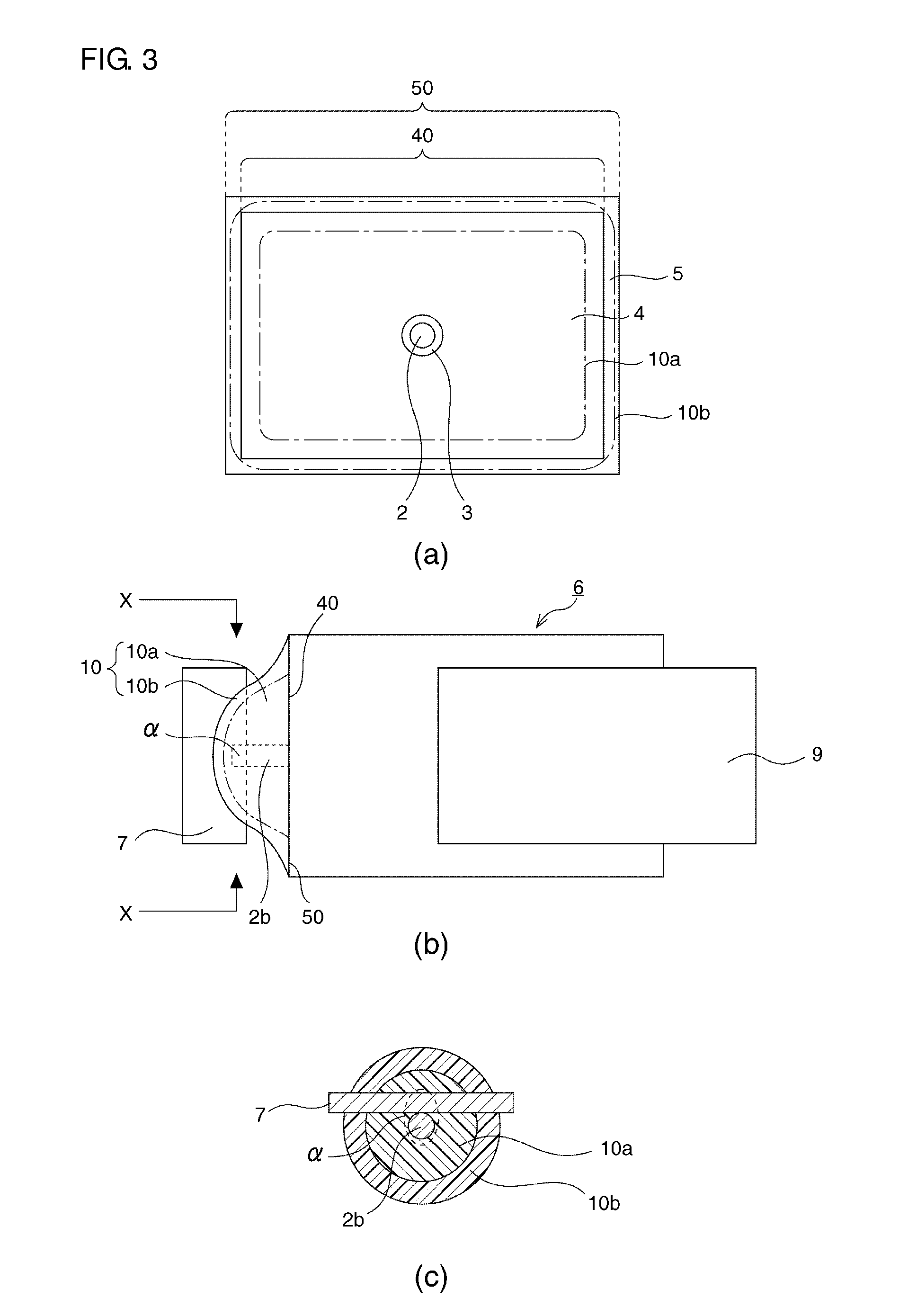
[0071]FIG. 6 is a cross-sectional view for schematically illustrating the interior of the solid electrolytic capacitor 21 according to this embodiment. Also in this embodiment, the exposed portion 40, the other end 2b of the anode lead 2 and the connecting part α are covered with a resin layer 10.

[0072]As shown in the figure, a first resin layer 10a is formed to cover the connecting part α, then extend around the anode lead 2 and then cover the entire surface of the exposed portion 40. A second resin layer 10b is formed to cover the first resin layer 10a, fully cover the surface 50 of the capacitor element and lie partly on other surfaces of the capacitor element beyond the surface 50.

[0073]This structure also performs the same eff...

third embodiment

[0075]Next will be described below a solid electrolytic capacitor 22 according to a third embodiment. Note that the following description is made mainly of the formation of a resin layer 10, which is a difference from the previously described first embodiment.

[0076]FIG. 7 is a cross-sectional view for schematically illustrating the interior of the solid electrolytic capacitor 22 according to this embodiment.

[0077]As shown in the figure, a first resin layer 10a is formed on part of the exposed portion 40 and around part of the other end 2b of the anode lead 2, but does not exist around the connecting part α. Instead of this, a second resin layer 10b is formed to cover the connecting part α and cover substantially the entire surface of the exposed portion 40.

[0078]Although this embodiment has the above structure, part of the exposed portion 40 is covered with the first resin layer 10a softer than the second resin layer 10b.

[0079]Therefore, the first resin layer 10a can reduce the str...


PUM


Abstract

A solid electrolytic capacitor includes at least one capacitor element in which the other end of an anode lead extends beyond an exposed portion of an electrolyte layer exposed from a cathode layer. The solid electrolytic capacitor further includes: an anode terminal connected to the other end of the anode lead, a cathode terminal connected to the cathode layer, a resin layer and a resin outer package covering the capacitor element and the resin layer. The resin layer covering the exposed portion of the electrolyte layer, the other end of the anode lead, and a connecting part between the other end of the anode lead and the anode terminal. The resin layer includes a first resin layer covering the exposed portion and a second resin layer covering the first resin layer, the first resin layer being softer than the second resin layer.

Description

BACKGROUND OF THE INVENTION[0001]1. Field of the Invention[0002]This invention relates to solid electrolytic capacitors having a resin outer package.[0003]2. Description of Related Art[0004]FIG. 17 shows in cross section the structure of a conventional solid electrolytic capacitor.[0005]As shown in the figure, a conventional solid electrolytic capacitor 120 has a capacitor element 106 that includes: an anode 101 made of a valve metal; an anode lead 102 provided in the anode 101 and having one end 102a embedded in the anode 101 and the other end 102b extending from the anode 101; a dielectric layer 103 formed by anodizing the anode 101; an electrolyte layer 104 formed on the dielectric layer 103; and a cathode layer 105 formed on the electrolyte layer 104. The anode 101 and the anode lead 102 are joined and integrated together by embedding the anode lead 102 into a powdered mass of a valve metal to extend the other end 102b of the anode lead from the powdered mass, pressing the powde...

Claims


Application Information

Patent Timeline
Patent Type & Authority Applications(United States)
IPC IPC(8): H01G9/08
CPCH01G9/012H01G9/15H01G9/08
Inventor UMEMOTO, TAKASHIHAYASHI, NOBUHIKO
Owner SANYO ELECTRIC CO LTD
Why Eureka
Try Eureka