Implant and a system and method for processing, desiging and manufacturing an improved orthopedic implant

a technology for orthopedic implants and implants, applied in the field of orthopaedic implants, can solve the problems of rod failure, rod failure, rod failure, etc., and achieve the effects of high fatigue load, long implant duration, and high fatigue strength

Inactive Publication Date: 2010-09-30
X SPINE SYST
View PDF76 Cites 9 Cited by
  • Summary
  • Abstract
  • Description
  • Claims
  • Application Information

AI Technical Summary

Benefits of technology

[0013]An object of the invention is to provide a dynamic stabilization device that has flexibility to accommodate the...

Problems solved by technology

The rods are subject to fatigue failure at high cycle/high load conditions.
The typical failure mode is a fatigue crack of the rod at either a midpoint of the rod shaft or at a connection point with the screw or rod connector.
If the loads exceed this value after they are implanted in the patient, the rods will fail and have to be removed surgically.
In implanted rigid devices, fatigue failure occurs at a rate of approximately 0.5-1%.
Such failures typically occur in patients where there are an abnormally high loads placed upon the implant.
This c...

Method used


Image

  • Implant and a system and method for processing, desiging and manufacturing an improved orthopedic implant
  • Implant and a system and method for processing, desiging and manufacturing an improved orthopedic implant
  • Implant and a system and method for processing, desiging and manufacturing an improved orthopedic implant

Examples


Embodiment Construction

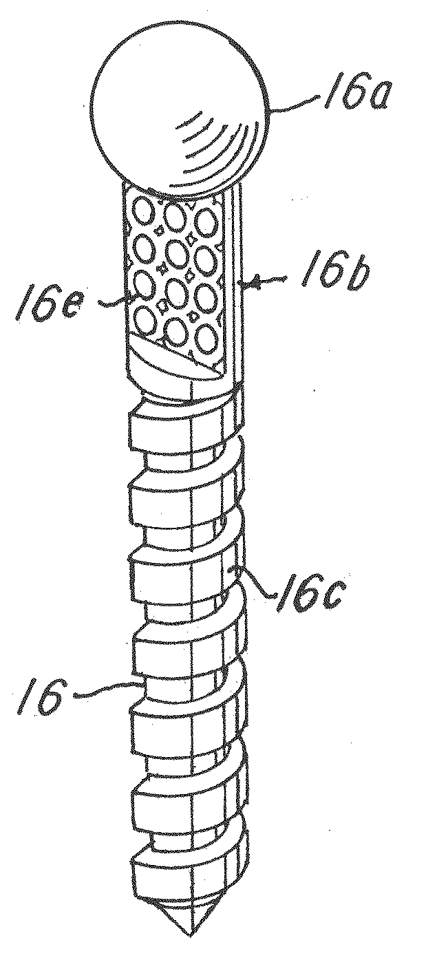
[0056]Referring now to FIGS. 4-15, an implant, system and method for making an implant, such as an orthopedic implant plate 12 (FIG. 8), rod 14 (FIG. 9) and screw 16 (FIG. 10) are shown. For purposes of illustration, an implant in the form of the rod 14 will be described, with it understood that the implant could be any implant, such as those mentioned herein, capable or adapted to be processed and made in accordance with the system and method described herein. One illustrative system, methodology or process for making a dynamic, flexible medical or orthopedic implant, such as the spinal fixation rod 14, disk augmentation system, plate 12, polyaxial screw 16 and the like, will now be described relative to FIGS. 4-11.

[0057]The system 200 (FIGS. 7A-7B) and a related process or procedure (FIGS. 4-6) begins at block 100 (FIG. 4) wherein an orthopedic implant, such as the orthopedic implant plate 12 (FIG. 8), rod 14 (FIG. 9) or polyaxial screw 16 (FIG. 10), is selected and designed or re...


PUM

PropertyMeasurementUnit
Lengthaaaaaaaaaa
Thicknessaaaaaaaaaa
Concentrationaaaaaaaaaa

Abstract

A medical or orthopedic implant, system and method for making the implant having areas that are designed to optimize compressive stress processing by, for example, laser shock peening. The implant is designed by identifying stress areas as processing zones. The processing zones are machined, processed or adapted to have a desired shape or configuration to optimize compression. The processed zones or areas are compressive stressed processed to have a higher density at zones or areas compared to areas that are not compressive stress processed. The implant is finished processed and sterilized and ready for use in the patient.

Description

CROSS-REFERENCE TO RELATED APPLICATION[0001]The present application claims priority to provisional U.S. Application Ser. No. 61 / 162,697 filed Mar. 24, 2009, to which Applicant claims the benefit of the earlier filing date. This application is incorporated herein by reference and made a part hereof.BACKGROUND OF THE INVENTION[0002]1. Field of the Invention[0003]This invention relates to orthopedic implants and, more particularly, to improved orthopedic implants and a method and system for making such orthopedic implants.[0004]2. Description of the Related Art[0005]Implanted instrumentation such as pedicle screw system is a mainstay of spinal fixation procedures in the thoracic and lumbar spine. These implants are used to help join vertebrae together and restore stability. Traditionally, spinal implant products have been rigid constructs designed to hold the spine immovably in place. Rigid fixation allows for an irreversible biological fusion of the vertebrae together. The natural mec...

Claims


Application Information

Patent Timeline
IPC IPC(8): A61F2/02A61B17/86B23K26/00
CPCA61B17/7002A61B17/7004A61F2002/3097A61F2/30767A61F2002/30922A61B17/866
Inventor KIRSCHMAN, DAVID LOUISMANNAVA, SEETHA RAMAIAHVASUDEVAN, VIJAY K.
Owner X SPINE SYST
Why Eureka
Try Eureka