
Inline chlorinator with integral control package, heat dissipation and warranty information accumulator

a chlorinator and control package technology, applied in the field of water purification, can solve the problems of unstable ozone chemical, unusable byproducts, and neither system leaves a residual disinfectant in the water supply, and achieves the effect of convenient maintenance and user-friendly

Inactive Publication Date: 2010-09-30
PENTAIR WATER POOL & SPA INC
View PDF36 Cites 53 Cited by
  • Summary
  • Abstract
  • Description
  • Claims
  • Application Information

AI Technical Summary

Benefits of technology

[0015]An object of the invention is to provide an inline chlorinator unit that is user friendly and easy to maintain for the owner, requiring few if any special service calls by a professional for repair and replacement.
[0016]An object of the invention is to a more reliable, robust inline chlorinator with enhanced controls and an enhanced and improved user interface features.
[0026]The controller unit can further comprise a microprocessor controller. The inline chlorinator can further comprise an at least one sensor in communication with the microprocessor controller. The at least one sensor can further comprise a flow sensor. The flow sensor is mounted within the chlorinator. The at least one sensor can also further comprise an electric potential sensor. The electrical potential sensor can measure the electrical potential across the at least one electrolytic plate and communicate the result to the controller unit. Upon detection of a threshold electrical potential input from the at least one electrical potential sensor, a voltage reversing circuit can be engaged and the polarity of the plates reversed to reduce buildup.

Problems solved by technology

For instance, some systems use chlorine dioxide, which is unstable and may produce undesirable byproducts such as chlorates.
However, ozone is an unstable chemical and breaks down rapidly as does UV radiation (ultra violet light) from UV treatment systems.
Additionally, neither of these systems leaves a residual disinfectant in the water supply.
However, even though chlorine is relatively inexpensive and safe as compared to other types of sanitizers, the cost of chlorine in tablet and liquid systems, like those used to typically sanitize a pool, becomes an extremely expensive proposition over the lifetime of the pool.
Moreover, significant hazards, time, labor, and other costs are associated with storing and handling toxic chlorine and / or other hazardous chemicals such as chlorine tablets, oxidizers, algaecides or algae inhibitors.
Another problem with the use of tablet and liquid based chlorine systems, like that shown in U.S. Pat. No. 6,656,353 is the need to stabilize the chlorine such that it remains in the water, as UV rays tend to deplete or damage chlorine molecules during the day.
However, these agents can build up to undesirable levels which can present a health problem and cause damage to pool plaster and can require draining the body of water and adding fresh water to reduce concentrations.
However, besides the problems already mentioned above, such devices tend to have significant reliability problems and / or require complex chemical production and containment requirements.
Moreover, such systems tend to require a professional to install and maintain resulting in expensive installation and maintenance costs.
This results in the locating of controls and electronics, which are negatively affected by the increased operating temperatures, remotely from the chlorinator.
This increases the complexity in these existing devices, as electrical connections must extend from the chlorinator to the controller and back to the chlorinator to properly function.
Generally, electrical systems, especially complex systems with multiple connections, in close proximity with salt water can be dangerous in and of themselves and may tend to cause accidental electrical shock hazards under some conditions.
This is coupled with the fact that these systems are also subject to electrical shorting in the normal course of operation, which causes breakdowns, an absence of chlorination during the breakdowns, repair expenses, and other problems.
These chlorinators work to the extent that they do satisfactorily treat the water, but they have serious drawbacks.
Essentially, they have very limited life spans without maintenance and are thus both inconvenient and expensive to maintain in full working order.
This results in downtime and potentially significant additional costs for these systems and inconvenience, in the case of pool systems, for the pool owner.
However, in each of the instances, several electrical connections are required to make the system functional and the systems are therefore still difficult to maintain for the average pool owner.
The significant maintenance, repair and operation costs involved with such systems can be disappointing to pool owners who were led to believe their system would reduce costs by eliminating the need to purchase chlorine.
None of these systems to date has been able to locate all the mechanical and electrical components in one easy to use and easy to replace “plug and play”, in-line package incorporating both the electrolytic components used for generating the chlorine and the control and power management components in a single housing together with a heat dissipation system to protect these electrical elements.
The prior art discussed above does not provide a long life, low maintenance, purification system that is an extremely effective purifying water and which incorporates its controller in situ on the inline device and, in an exemplary embodiment, utilizes a heat sink element to help cool the electronics.

Method used


Image

  • Inline chlorinator with integral control package, heat dissipation and warranty information accumulator
  • Inline chlorinator with integral control package, heat dissipation and warranty information accumulator
  • Inline chlorinator with integral control package, heat dissipation and warranty information accumulator

Examples


Embodiment Construction

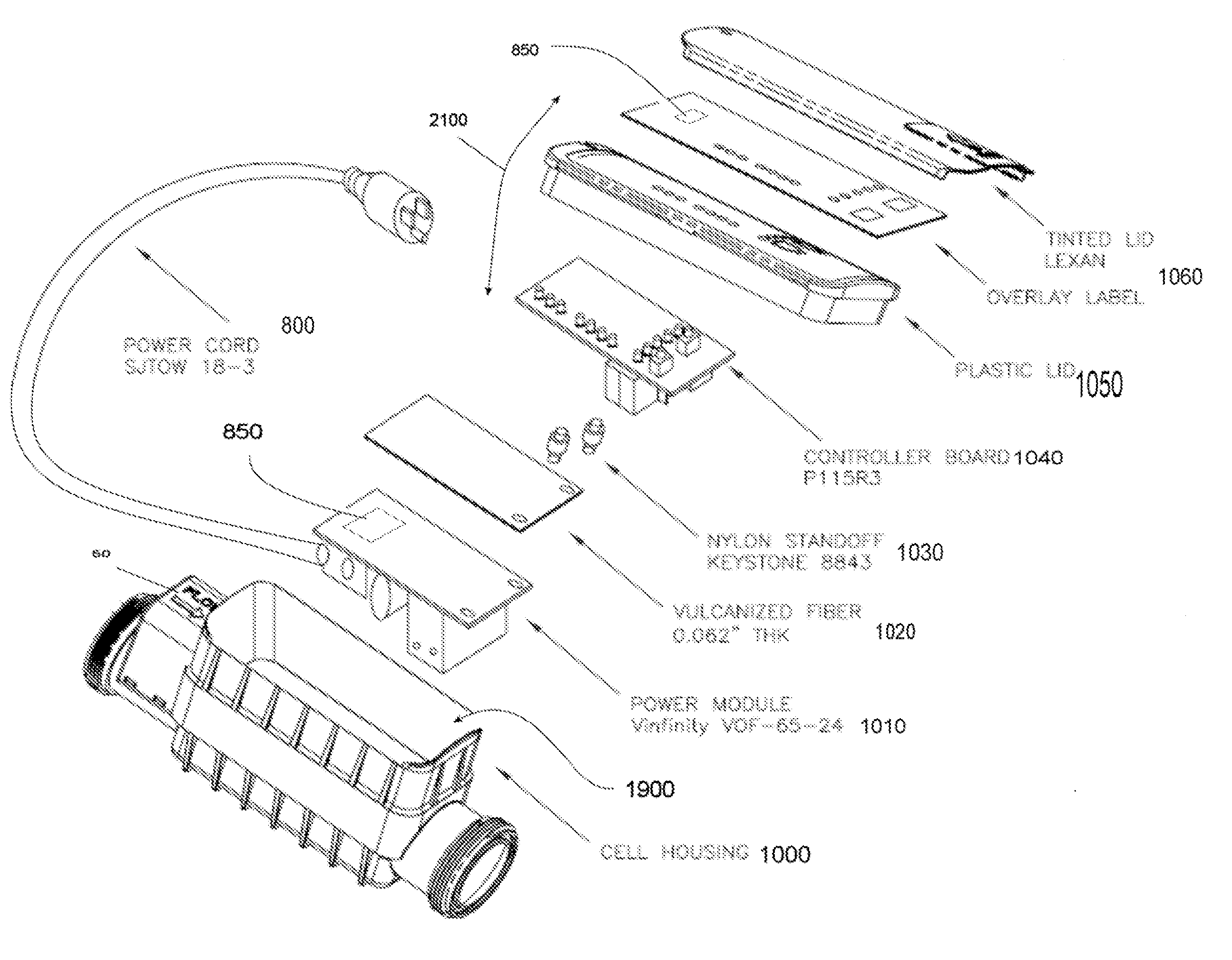
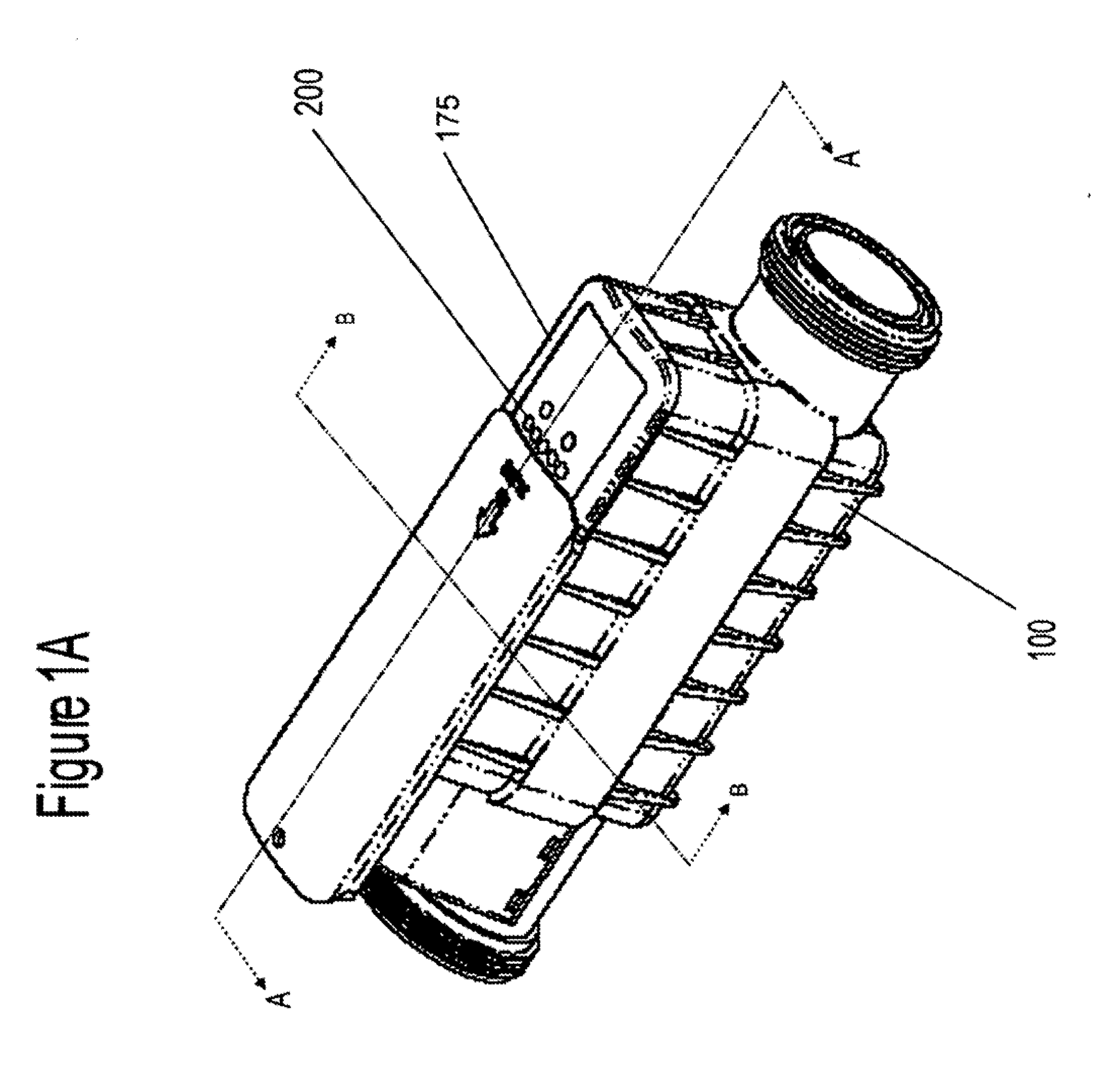
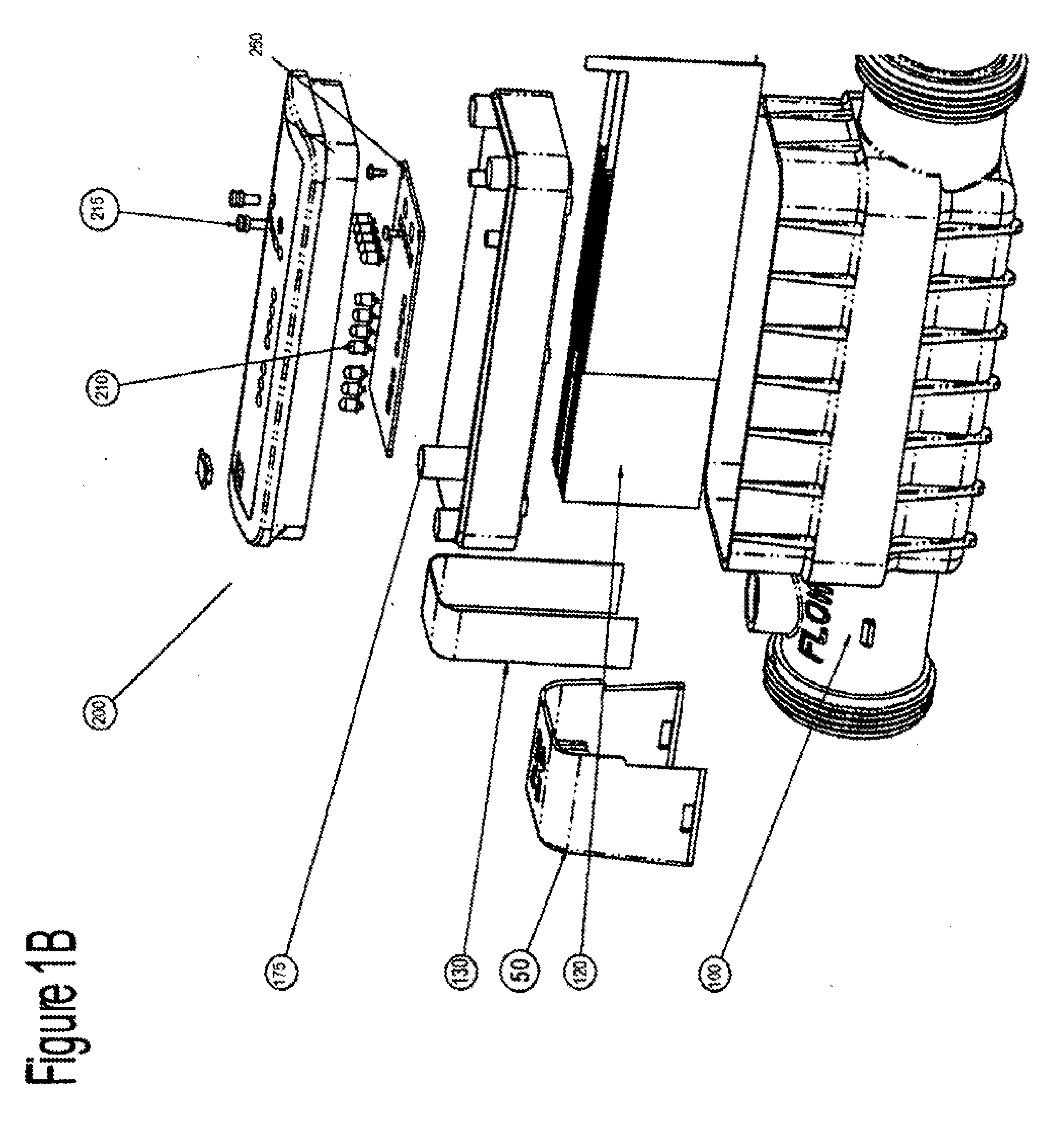
[0048]FIG. 1A shows an isometric view of an exemplary embodiment of the instant invention and FIG. 1B illustrates an exploded view of the exemplary embodiment of FIG. 1A. The system is designed to be put inline with a water input line. The chlorinator or chlorinator unit has a housing 100. The housing may be comprised of any suitable material and is a unitary housing in the exemplary embodiment. This material may be, for instance, but is not limited to a heavy-duty plastic or any suitable material which has sufficient durability in the highly chlorinated environment.

[0049]The housing 100 has an inflow or input side 150 wherein water flows into the chlorinator. A flow switch 50 is included with a cover. The water passes through the housing and through a series of electrolytic plates 120. The electrolytic plates 120 are typically matched sets of anode and cathode plates comprising copper or other suitable materials to provide an electrical current sufficient to separate the chlorine f...


PUM

PropertyMeasurementUnit
poweraaaaaaaaaa
inductanceaaaaaaaaaa
resistanceaaaaaaaaaa

Abstract

An inline chlorinator with a housing having an inlet end and an outlet end in communication with the swimming pool bringing water from the pool through the inlet end and back to the pool from the outlet end and an upper compartment having an electronics section is provided. It includes a power source coupling and an at least one sensor sensing changes in the power source coupling. A controller unit contained within the electronics section, the controller unit being electrically coupled to a power source and an at least one electrolytic plate. An at least one hours of operation counter is provided. A heat sink member is also provided and is in thermal communication with the controller, where the flow of the water in the swimming pool water purification system cools the heat sink member, controller unit, and the electronics in the electronics section. Where the heat sink is separated from the water coming in the inlet end by a separation section, the separation section being a concurrent wall of the electronics compartment and the separation section in direct contact with the water coming from the pool at the inlet end, the separation section being in direct contact with the heat sink and both the heat sink and the separation section being continually cooled by the water flowing in through the inlet end of the housing.

Description

PRIORITY DATA[0001]This application claims benefit of earlier filed U.S. Provisional Patent Application Ser. No. 60 / 621,806 entitled “Inline Chlorinator with Integral Control Package and Heat Dissipation” filed on Oct. 26, 2004, and is a continuation in part application of U.S. patent application Ser. No. 11 / 258,136, entitled “Inline Chlorinator with Integral Control Package and Heat Dissipation”, filed on Oct. 26, 2005, both being herein incorporated by reference.TECHNICAL FIELD[0002]The present invention relates generally to water purification and, in an exemplary embodiment, to a chlorine generator, which produces unexpected benefits of increased reliability, decreased maintenance costs, and improved water purification through an inline chlorination device with an integral controller, a heat sink member, a power source connector and an accumulator for warranty tracking information for easy maintenance and replacement.BACKGROUND OF THE INVENTION[0003]There are various methods of d...

Claims


Application Information

Patent Timeline
Patent Type & Authority Applications(United States)
IPC IPC(8): G06Q10/00E04H4/16B01D35/00G06Q50/00
CPCC02F1/4674C02F2103/42C02F2201/46125G06Q30/012C02F2201/46145C02F2209/008C02F2201/4613
Inventor DOYLE, KEVINJOHNSON, BRUCESHULTE, KEITH
Owner PENTAIR WATER POOL & SPA INC
Learn More