Spray Lubrication Unit And Method For Rolling Cylinders

a technology of lubrication unit and rolling cylinder, which is applied in the direction of machines/engines, manufacturing tools, mechanical apparatus, etc., can solve the problems of difficult to ensure the controllability of the friction coefficient obtained, difficult to maintain the stability, and difficulty in maintaining the stability, so as to eliminate the risk of fire, prevent obstruction of pipes and nozzles, and facilitate maintenance

Active Publication Date: 2010-10-14
CENT DE RECH METALLURGIQUES CENT VOOR RES IN DE METALLURGIE
View PDF19 Cites 15 Cited by
  • Summary
  • Abstract
  • Description
  • Claims
  • Application Information

AI Technical Summary

Benefits of technology

[0028]The invention also has the aim of precise and economical use of the lubricant at a very low flow rate for the same efficiency.
[0030]The invention has the further aim of easy maintenance, thanks in particular to the fact that obstruction of the pipes and nozzles is prevented.
[0031]The invention has the further aim of eliminating the risk of fire and of reducing pollution by the lubricant.

Problems solved by technology

The point of good lubrication of the working rollers is not simply restricted to the problem of the performance of the rollers (surface deterioration) but is also associated with the rolling forces and torques to be applied, and hence with the required electricity consumption.
When used on an industrial scale, the main drawbacks inherent in these devices for spraying an oil emulsion are the following:the oil-water interaction, which depends on the type of oil and on the “quality” of the water, determines the time for the oil to adhere to the roller as well as the quantity that adheres.
In fact, it is difficult to maintain this stability between the static tube mixer and the various jets; in other words, it is difficult to ensure the controllability of the friction coefficient obtained;bringing the oil and water into contact usually leads to reactions that form a hard, adhesive polymer phase, blocking the feeder pipes and the jets.

Method used


Image

  • Spray Lubrication Unit And Method For Rolling Cylinders
  • Spray Lubrication Unit And Method For Rolling Cylinders
  • Spray Lubrication Unit And Method For Rolling Cylinders

Examples


example 1

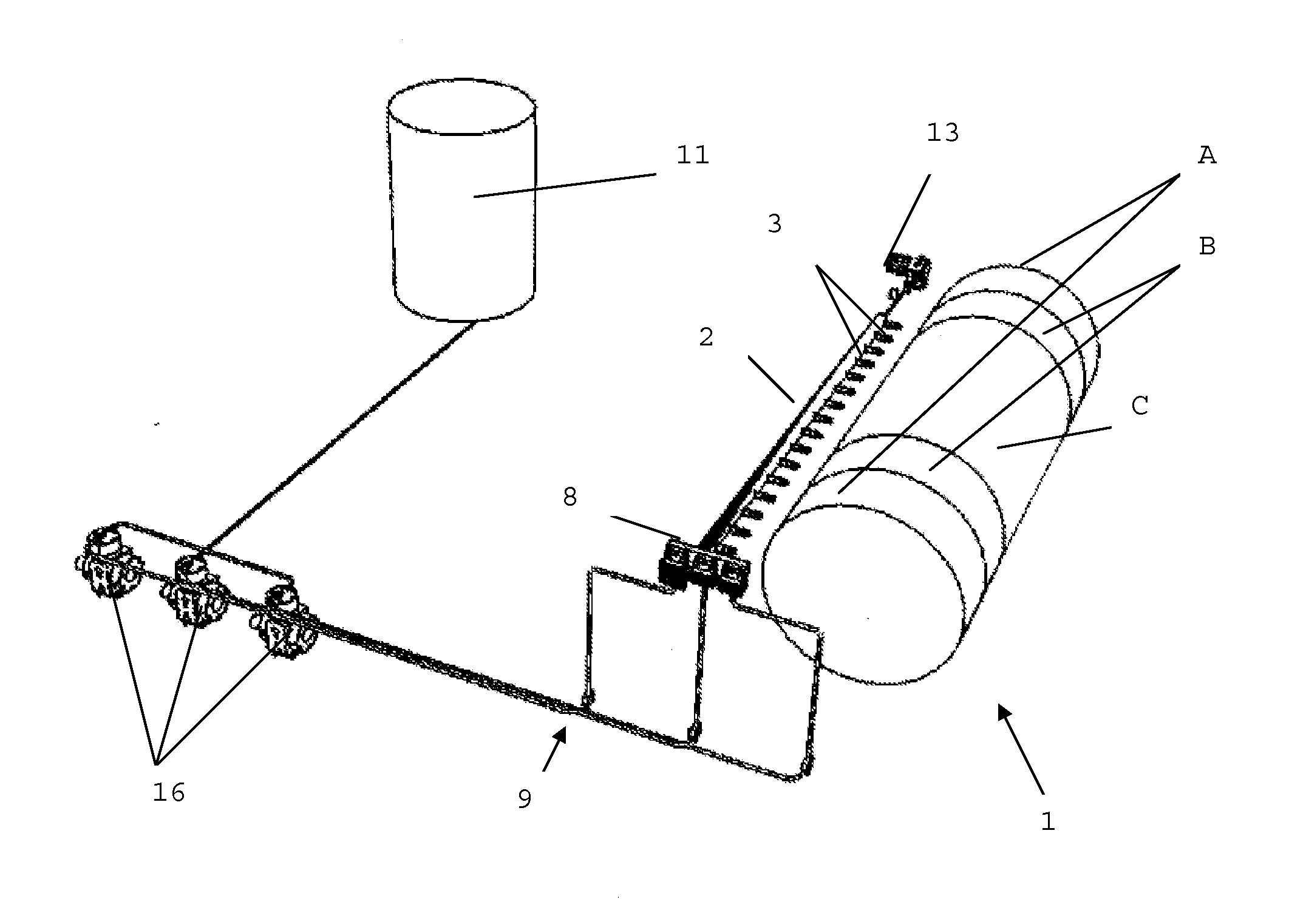
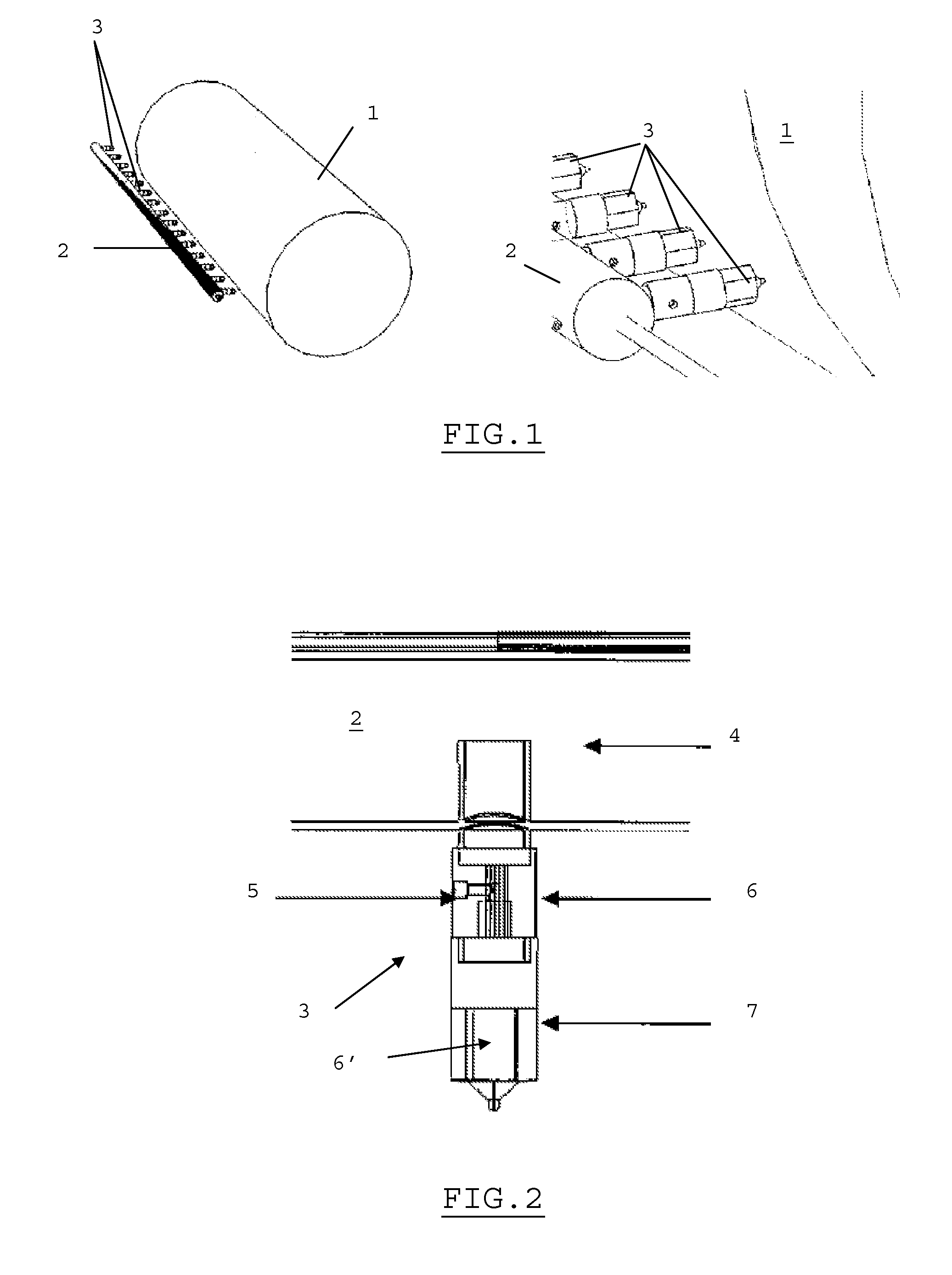
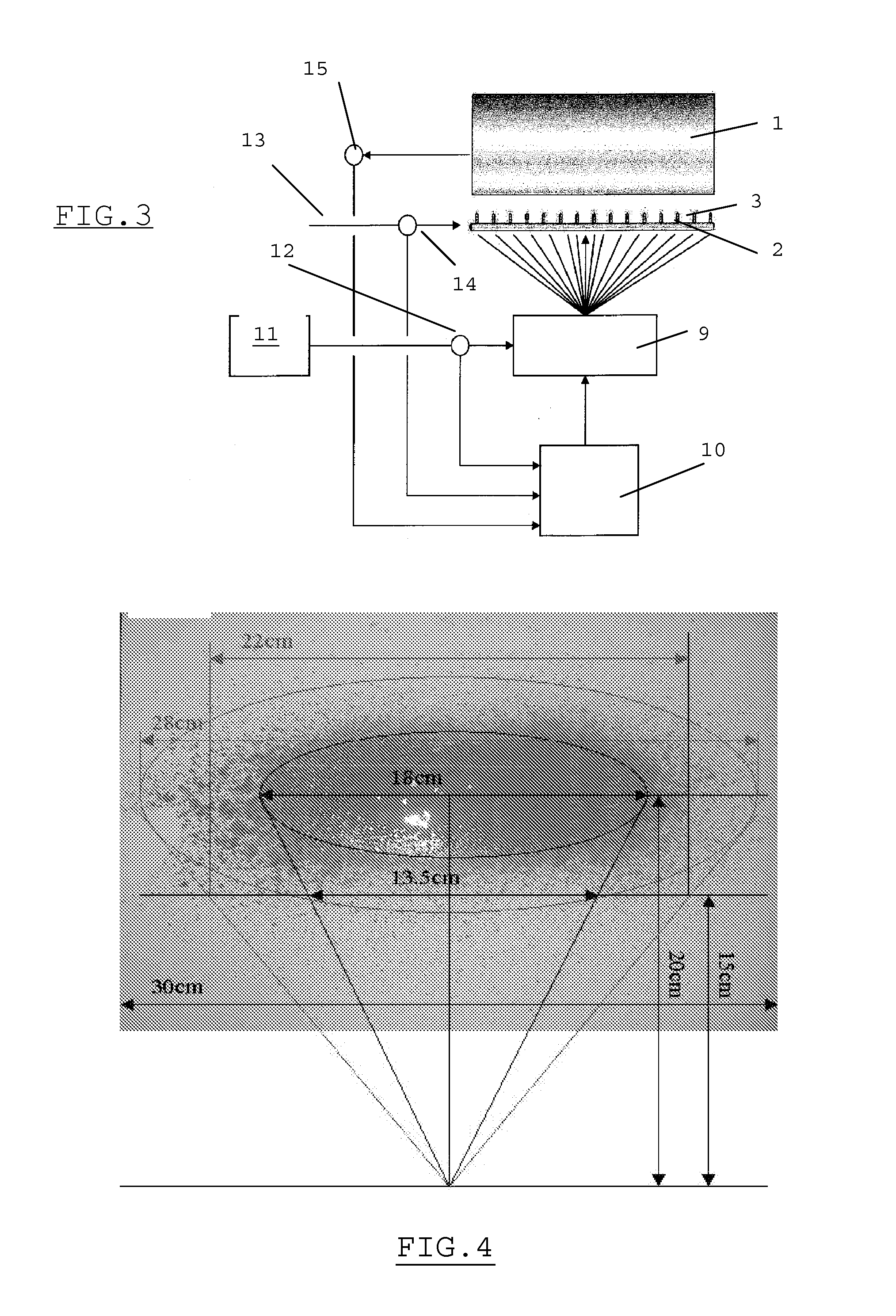
[0050]According to a first preferred embodiment of the invention, shown in FIG. 1, the lubrication device comprises a bar 2 of air sprays 3 positioned in parallel to the rolling cylinder 1. The sprays 3 are arranged along this bar 2, perpendicular to it, preferably equidistant from each other. The distance between the bar and the roller is preferably between 100 and 200 mm.

[0051]FIG. 2 shows the detail of a spray 3 made of stainless steel. It comprises an compressed air inlet 4, an unpressurised oil inlet 5, both inlets being located by a specially designed adapter 6 followed by a mixing chamber 6′ where the oil and air are mixed, and a nozzle 7 for the release of the atomised mixture. The adapter 6 located after the air manifold 4 thus allows the transport of air and the supply of oil via the inlet 5. It also plays a part in securing the nozzle (support).

[0052]As an advantage, about fifteen sprays 3 will be provided per bar 2, allowing a treatment width of 2 m, with for example a m...

example 2

[0056]According to a second preferred embodiment of the invention, shown in FIG. 5, the bar 2 of air sprays arranged in parallel to the rolling cylinder 1 is supplied with oil coming from the tank 11 along parallel lines equipped with dosing pumps 16, each one opening, by an inlet 17, into a modular divider valve 8 (MDV, see FIG. 6) located at one end of the bar 2 and with multiple outlets 18 supplying the sprays 3 positioned on the bar 2. An additional On / Off valve (not shown) may be installed in the parallel oil pipes supplying the divider 8 and just before it for reasons of ease of use of the installation.

[0057]An example of an MDV divider 8 with six outlets 11 sold by Lubriquip Inc., Cleveland, Ohio (USA) is shown in FIG. 6. A sequential supply cycle to the various outlet doors 18 is ensured by the movement of the pistons 19. The use of several valves allows to divide the roller to be lubricated into two or three zones, for example A, B, C. The air supply 13 is ensured at one en...


PUM

PropertyMeasurementUnit
sizeaaaaaaaaaa
distanceaaaaaaaaaa
distanceaaaaaaaaaa

Abstract

The present invention relates to an installation for the in-line lubrication of rolling cylinders (1), preferably for hot rolling of a metal strip, which is preferably steel, by spraying or atomising a lubricant over a target comprising said cylinders and / or said strip, preferably in the vicinity of the roll gap, by means of a bar (2) of controllable air sprays (3), arranged in parallel to said cylinders (1) and supplied with compressed air or inert gas (4), wherein each spray (3) comprises an inlet for the compressed air or inert gas (4) and an inlet for uncompressed pure oil (5) in an adapter (6) followed by a mixing chamber (6′) as well as an outlet nozzle (7) for the atomised mixture.

Description

FIELD OF THE INVENTION[0001]The present invention relates to a new lubrication unit for cylinders or rollers of a hot or cold rolling line.[0002]The invention also relates to the implementation method on the unit.TECHNOLOGICAL BACKGROUND AND STATE OF THE ART[0003]It is known that lubricating rolling cylinders in iron and steel mill is often achieved by spraying (or vaporising) an emulsion, which is a suspension of droplets of oil in water, with an oil concentration typically varying between 0.3 and 2%. It may either be a stable emulsion or an unstable emulsion prepared on the line.[0004]In general, the emulsion is directly applied to the working rollers by means of a spray device located after the scrapers with a view to applying the oil onto a dry surface. This application method ensures better distribution of the oil and as a result contributes to reducing oil consumption.[0005]The point of good lubrication of the working rollers is not simply restricted to the problem of the perf...

Claims


Application Information

Patent Timeline
Patent Type & Authority Applications(United States)
IPC IPC(8): F01M1/08B21B27/10
CPCB21B27/10
Inventor VERVAET, BARTUIJTDEBROEKS, HUGOLANNOO, GRIET
Owner CENT DE RECH METALLURGIQUES CENT VOOR RES IN DE METALLURGIE
Why Eureka
Try Eureka