Flying Saucer

a technology of flying saucers and saucers, which is applied in the field of flying saucers, can solve the problems of high energy consumption, clumsy flying, and complex flying operations and control systems, and achieve the effects of convenient changing directions, simple handling, and neutralizing nois

Inactive Publication Date: 2010-10-14
CHEN JIUBIN
View PDF7 Cites 7 Cited by
  • Summary
  • Abstract
  • Description
  • Claims
  • Application Information

AI Technical Summary

Benefits of technology

[0006]The advantages of this invention lie in: it utilizes circular motion fully, and the field's actions, and gyro's steadiness; whirling flywheel plays the role of gyro; flight altitude can be high or low; motivation device is fixed in the front of flying saucer; it can go forwards or upwards with jetting power produced by flywheel jet engine's high speed whirling; it can realize vertically taking off and landing; there fix capsule motion direction regulating equipment and capsule whirling steadiness regulating equipment; it is simple to handle; it flies smoothly and steadily; it is convenient in changing directions; in flying, flying saucer produces a spiral airflow around capsule and simultaneously spirally propels toward the underneath of capsule; sp

Problems solved by technology

Airplane has many flaws, for example, it has many limitations in many conditions when it takes off and lands, and most airplanes can not vertically take off or land; its flying speed is not high enough; it has a high energy consumption; its operating and controlling system is too complex in flying; it is clumsy in flying; it can not fly in certain weathers, etc.
Helicopter has problems of low flying speed, high energy consumption, and can

Method used


Image

  • Flying Saucer
  • Flying Saucer
  • Flying Saucer

Examples


Embodiment Construction

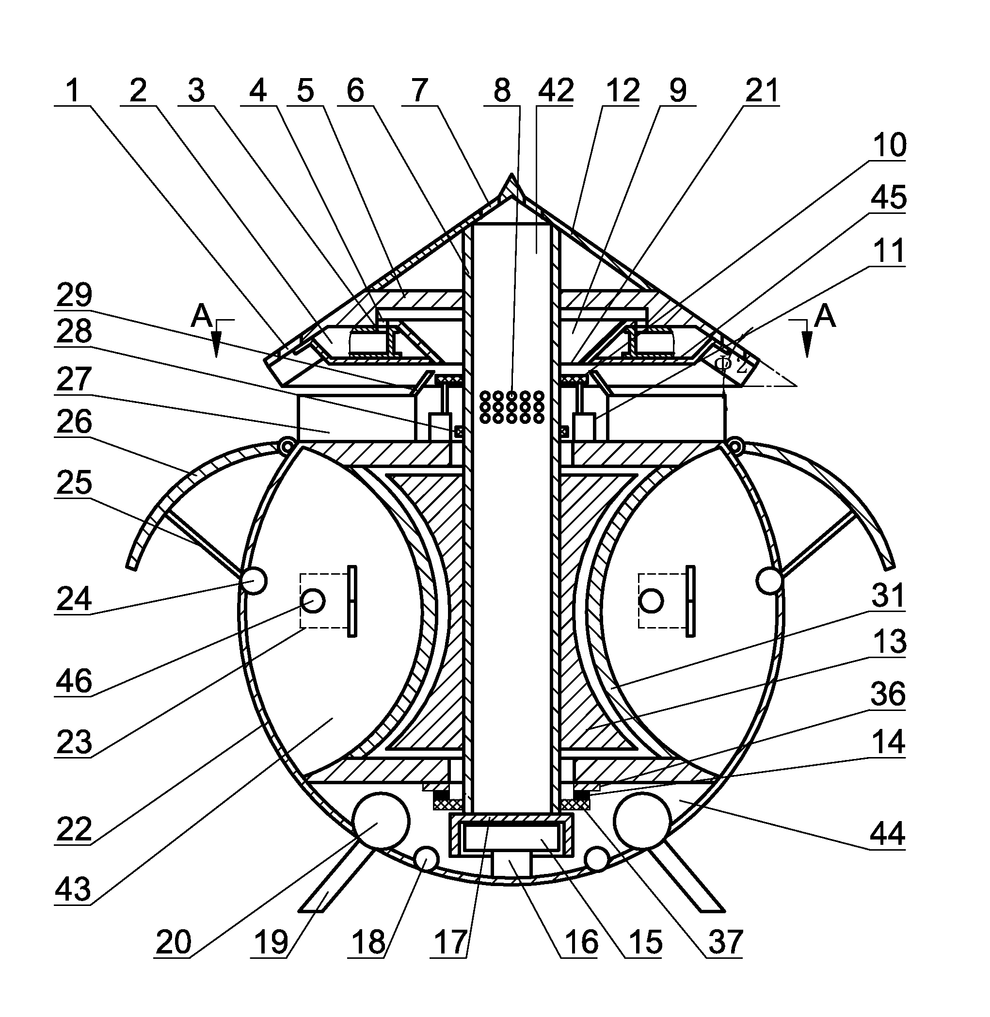
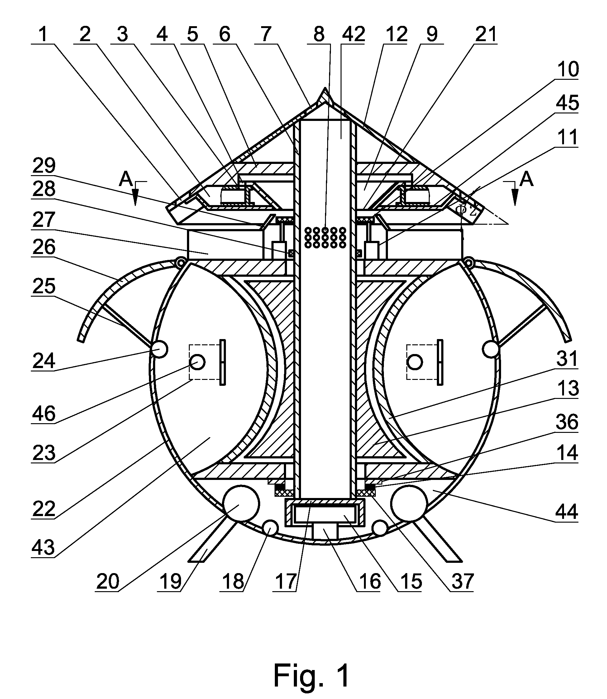
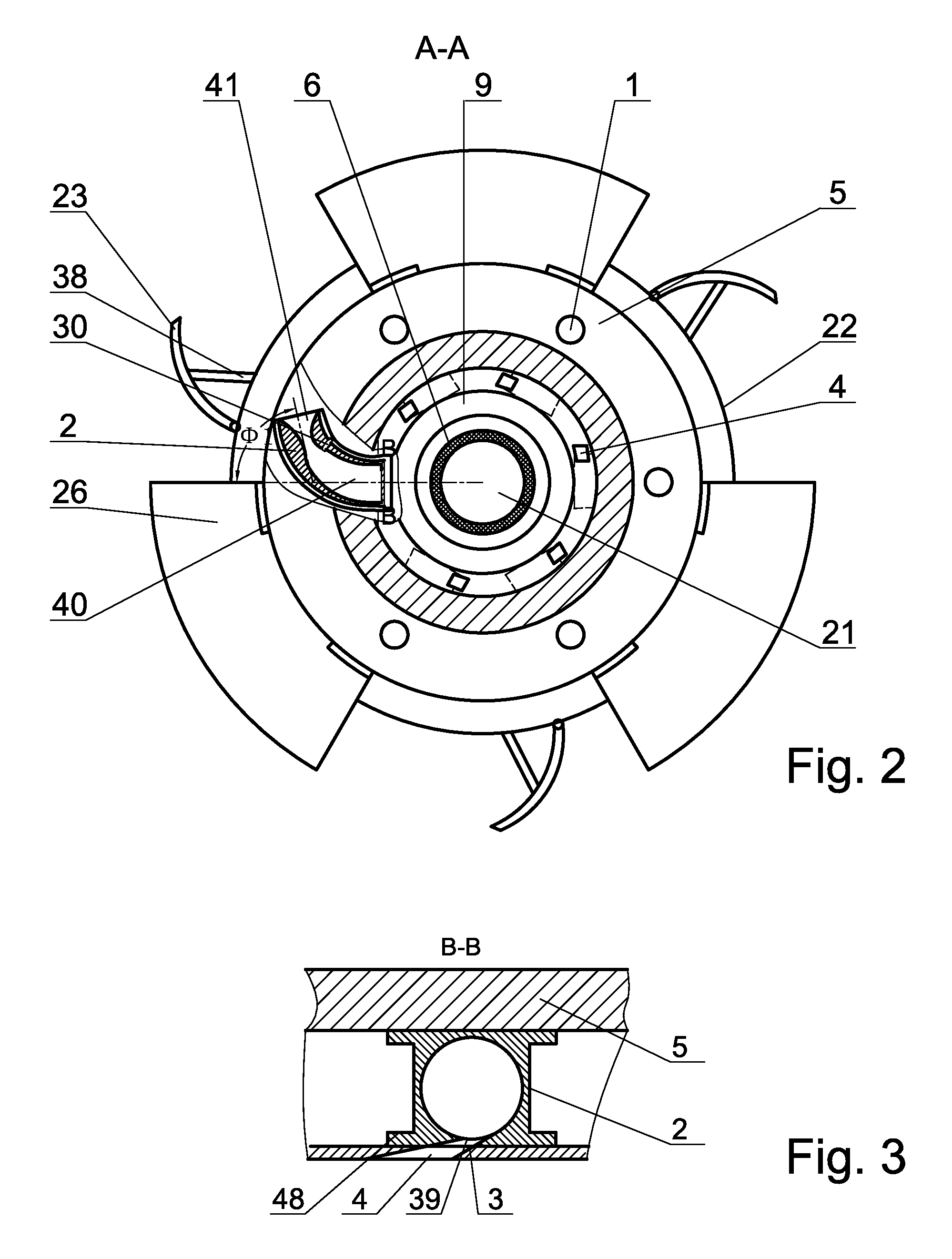
[0013]The main structure of this invention is: flying saucer includes capsule 22, operating and controlling system, engine electrical system, inner-cabin facilities, fuel system, start-up system and ignition system. On capsule 22 there fix capsule motion direction regulating equipment and capsule whirling steadiness regulating equipment. On capsule 22 there fix fuel tank 27. On fuel tank 27 there fix fuel pipe 29. On capsule 22 there fix flywheel jet engine also, which consists flywheel spindle 6, flywheel 5 and gas jetting device. Flywheel spindle 6 connects to capsule 22. On flywheel spindle 6 there fix flywheel 5. In the outer region of flywheel 5 there fix a plurality of gas jetting devices, the jetting direction of which makes an angle of Φ1 with the radius of flywheel 5. According to studies, the optimal value of Φ1 is among 55.62°-68.76°, which can help utilize a part centrifugal force to neutralize a majority of tremendous centrifugal force produced by high speed whirling. L...


PUM


Abstract

This invention provides a kind of flying saucer, which pertains to aviation vehicles area. It includes capsule, operating and controlling system, energy electrical system, inner-cabin facilities, fuel system, start-up system and ignition system. On capsule there fix capsule motion direction regulating equipment and capsule whirling steadiness regulating system. On capsule there fix fuel tank. On fuel tank there is a fuel tube. On capsule there fix a flywheel jet engine also, which includes flywheel spindle, flywheel and jetting device. Flywheel spindle connects to capsule. Flywheel is fixed on flywheel spindle. In the peripheral region of flywheel there fix several jetting devices. It can realize vertically taking off and landing. Capsule motion direction regulating equipment and capsule whirling steadiness regulating equipment are fixed on capsule. It can be simply handled, and it flies smoothly and steadily. It is convenient to change directions. In flight, flying saucer produces a spiral airflow whirling around capsule and simultaneously spirally propelling toward the bottom of capsule, which can boost the propelling speed toward the bottom of capsule. This invention has advantages of its high flying speed; it's flexible in changing directions; its high security; its low fuel costs, and so on.

Description

FIELD OF THE INVENTION[0001]This invention involves the field of flying vehicles. Specifically, it is a kind of flying saucer.BACKGROUND OF THE INVENTION[0002]Currently, available flying vehicles mainly include airplanes, helicopters, spacecrafts and rockets. Airplane has many flaws, for example, it has many limitations in many conditions when it takes off and lands, and most airplanes can not vertically take off or land; its flying speed is not high enough; it has a high energy consumption; its operating and controlling system is too complex in flying; it is clumsy in flying; it can not fly in certain weathers, etc. Helicopter has problems of low flying speed, high energy consumption, and can not fly in certain weathers, etc. Spacecraft has drawbacks of low flying speed; it cannot realize intergalactic flight; it has difficulties in taking off and landing; it has problems when entering atmosphere, etc. Generally, these flying vehicles are of low security, high maintaining and using...

Claims


Application Information

Patent Timeline
IPC IPC(8): B64C39/06
CPCB64C39/00B64C39/001
Inventor CHEN, JIUBIN
Owner CHEN JIUBIN
Why Eureka
Try Eureka