Organic electroluminescence element and manufacturing method thereof

a technology of electroluminescence elements and manufacturing methods, applied in the direction of basic electric elements, electrical apparatus, semiconductor devices, etc., to achieve the effects of excellent power consumption and driving life, reduced number of organic layers, and remarkable hole injection properties

Active Publication Date: 2010-10-14
JOLED INC
View PDF24 Cites 68 Cited by
  • Summary
  • Abstract
  • Description
  • Claims
  • Application Information

AI Technical Summary

Benefits of technology

[0024]The organic EL element according to an aspect of the present invention has a remarkable hole injection property, can reduce the number of organic layers, and can form an organic layer by wet printing. Accordingly, it is possible to provide an organic EL element that has excellent power consumption and driving life, and has a simple manufacturing process.

Problems solved by technology

However, the structure and the manufacturing method of the organic EL element disclosed in Patent Literatures 2 and 3 have the following problem.

Method used


Image

  • Organic electroluminescence element and manufacturing method thereof
  • Organic electroluminescence element and manufacturing method thereof
  • Organic electroluminescence element and manufacturing method thereof

Examples


embodiment 1

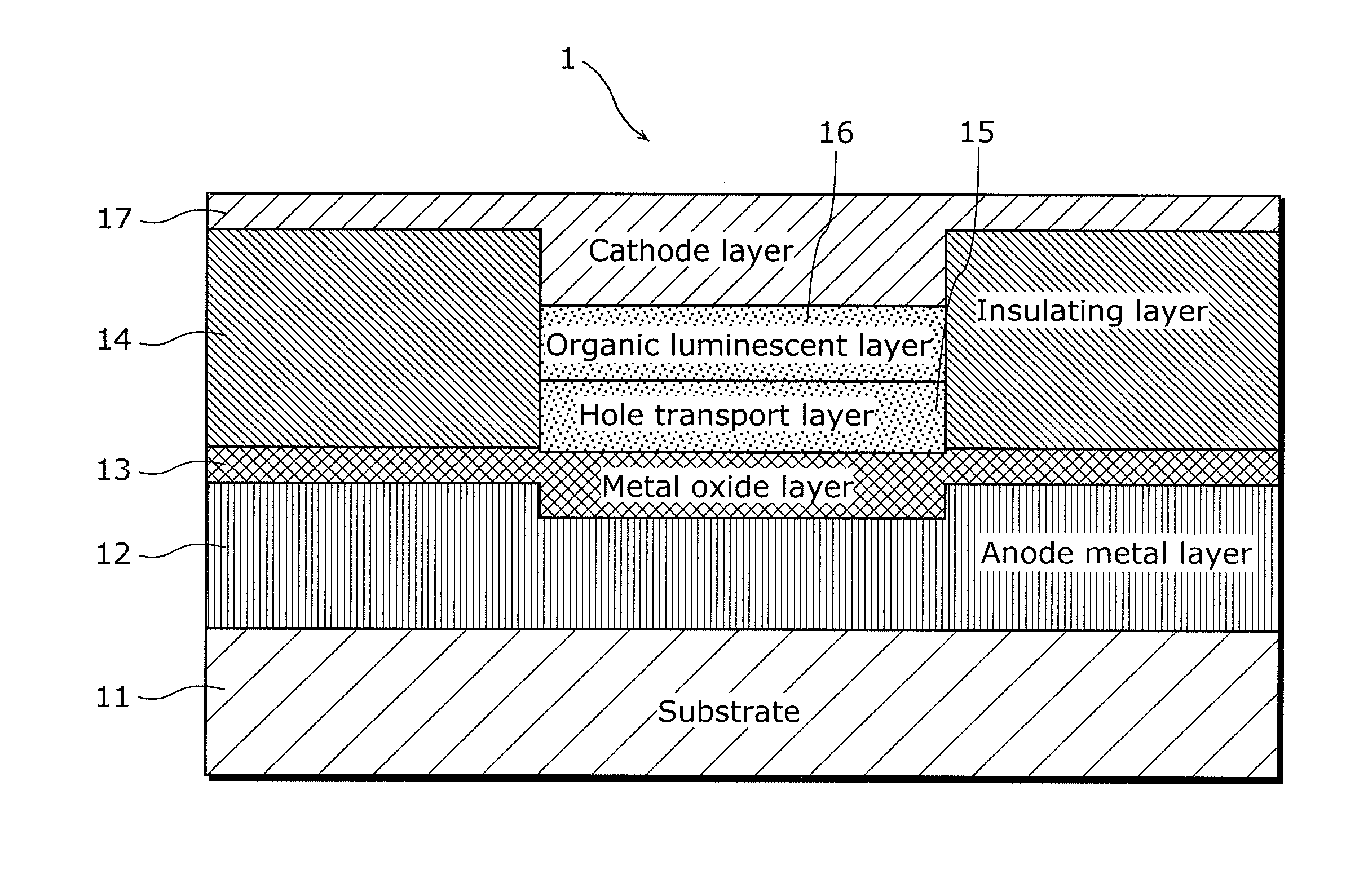
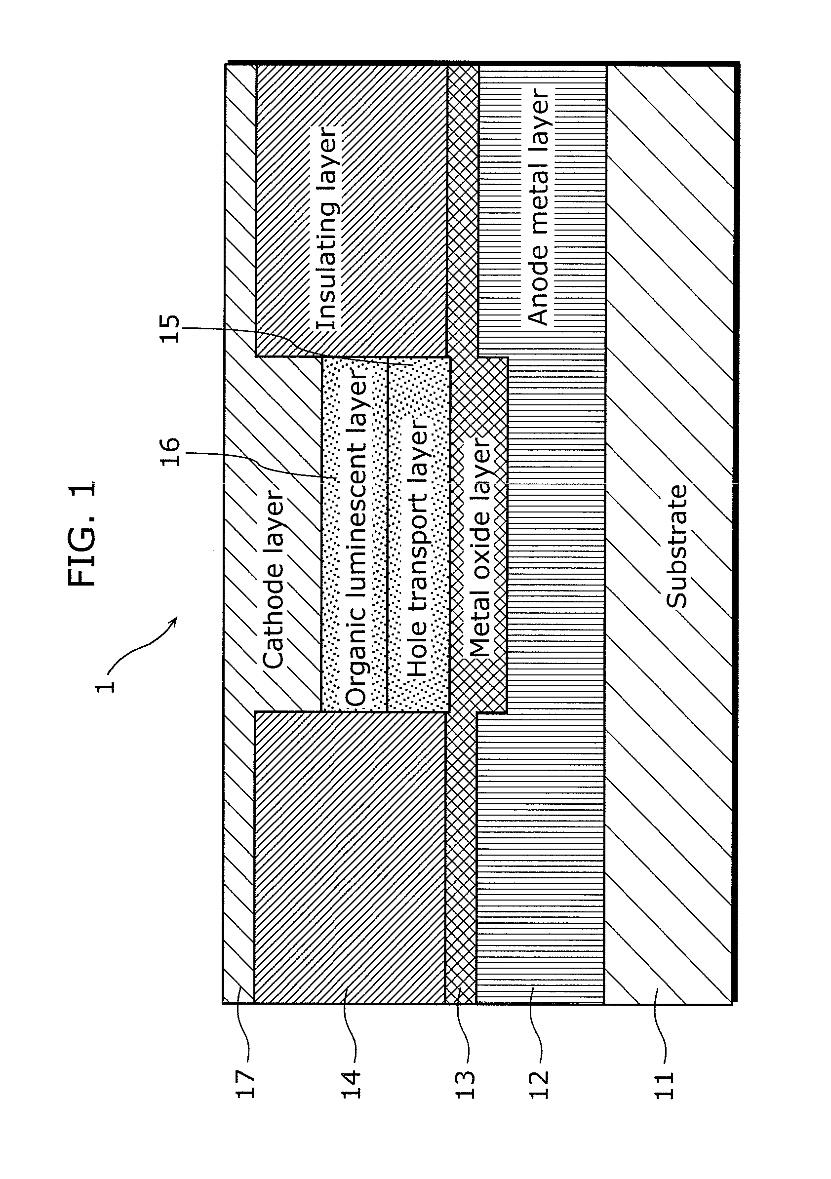
[0072]An organic electroluminescence element (hereinafter referred to as an organic EL element) according to this embodiment includes: an anode metal layer formed on a substrate; an insulating layer formed on the anode metal layer in a first region; a metal oxide layer formed on the anode metal layer, in the first region and a second region; a hole transport layer formed on the metal oxide layer in the second region where the insulating layer is not formed; an organic luminescent layer formed on the hole transport layer; and a cathode layer formed on the organic luminescent layer, in which an upper surface of the anode metal layer in the second region is located below an upper surface of the anode metal layer in the first region. This allows forming an organic layer that has superior hole injection property by wet printing and capable of reducing the number of organic layers.

[0073]The following specifically describes specific description of Embodiment 1 of the organic EL element acc...

example 1

[0125]FIG. 4 is a process chart describing a manufacturing method of an organic EL element according to Embodiment 1 of the present invention.

[0126]First, on the surface of a glass substrate 111 (using non-soda glass manufactured by Matsunami Glass Ind. Ltd.), an anode 123 having the thickness of 100 nm and made of 97% molybdenum and 3% chrome (hereinafter may be referred to as Mo:Cr (97:3)) was formed by sputtering Subsequently, after patterning the anode 123 by photolithography using photosensitive resist and etching and after delamination of the photosensitive resist patterns, patterning of the anode 123 into a predetermined shape of anode was performed.

[0127]A mixture of phosphoric acid, nitric acid, and acetic acid was used as an etchant.

[0128]After forming the anode 123 and before forming an insulating layer, the uppermost surface of the anode 123 is naturally oxidized, forming the surface oxidation film 131. Note that, as described earlier, there is a case where the surface o...

example 2

[0137]The organic EL element in Example 2 according to the present invention was formed in the same manner as Example 1, except that the cathode layer 171 in FIG. 4 is formed to have 5 nm of barium and 10 nm of silver (manufactured by Aldrich, purity 99.9%), and 80 nm of lithium fluoride was formed as a refractive index adjusting layer.


PUM

PropertyMeasurementUnit
reflectivityaaaaaaaaaa
thicknessaaaaaaaaaa
visible light reflectivityaaaaaaaaaa

Abstract

The organic electroluminescence element includes an anode metal layer above a substrate. The anode metal layer comprises an inner region and an outer region. The inner region is adjacent to and different than the outer region. An upper surface of the inner region is lower than an upper surface of the outer region. A metal oxide layer is on the inner region of the metal anode layer. A hole transport layer is above the metal oxide layer and the inner region. The hole transport layer comprises a hole-transporting organic material. An organic luminescent layer is above the hole transport layer and the inner region. A cathode layer is above the organic luminescent layer and the inner region. The cathode layer injects electrons into the organic luminescent layer. An insulating layer is above the outer region of the anode metal layer.

Description

CROSS REFERENCE TO RELATED APPLICATION[0001]This is a continuation application of PCT Application No. PCT / JP2009 / 004624 filed Sep. 16, 2009, designating the United States of America, the disclosure of which, including the specification, drawings, and claims, is incorporated herein by reference in its entirety.[0002]The disclosure of Japanese Patent Application No. 2008-241238 filed on Sep. 19, 2008, including the specification, drawings and claims, is incorporated herein by reference in its entirety.BACKGROUND OF THE INVENTION[0003]1. Field of the Invention[0004]The present invention relates to organic electroluminescence elements and manufacturing methods thereof, and particularly relates to an organic electroluminescence element used for a display device or lighting, and a manufacturing method thereof.[0005]2. Description of the Related Art[0006]An organic electroluminescence element (hereinafter referred to as an organic EL element), which has a structure in which an organic laye...

Claims


Application Information

Patent Timeline
Patent Type & Authority Applications(United States)
IPC IPC(8): H01L51/52H01L51/56
CPCH01L51/5088H01L51/5271H01L51/5206H10K50/17H10K50/813H10K50/818H10K50/856H10K2102/351H10K50/81H10K50/00
Inventor OKUMOTO, KENJIYOSHIDA, HIDEHIRO
Owner JOLED INC
Why Eureka
Try Eureka