Clock Circuit and Method for Pulsed Latch Circuits
a clock circuit and latch circuit technology, applied in the direction of pulse manipulation, pulse technique, generating/distributing signals, etc., can solve the problems of significant power consumption, significant silicon area, and further increase the power consumption problem by the consumption of power
- Summary
- Abstract
- Description
- Claims
- Application Information
AI Technical Summary
Benefits of technology
Problems solved by technology
Method used
Image
Examples
Embodiment Construction
[0033]The making and using of the presently preferred embodiments are discussed in detail below. It should be appreciated, however, that the present invention provides many applicable inventive concepts that can be embodied in a wide variety of specific contexts. The specific embodiments discussed are merely illustrative of specific ways to make and use the invention, and do not limit the scope of the invention.
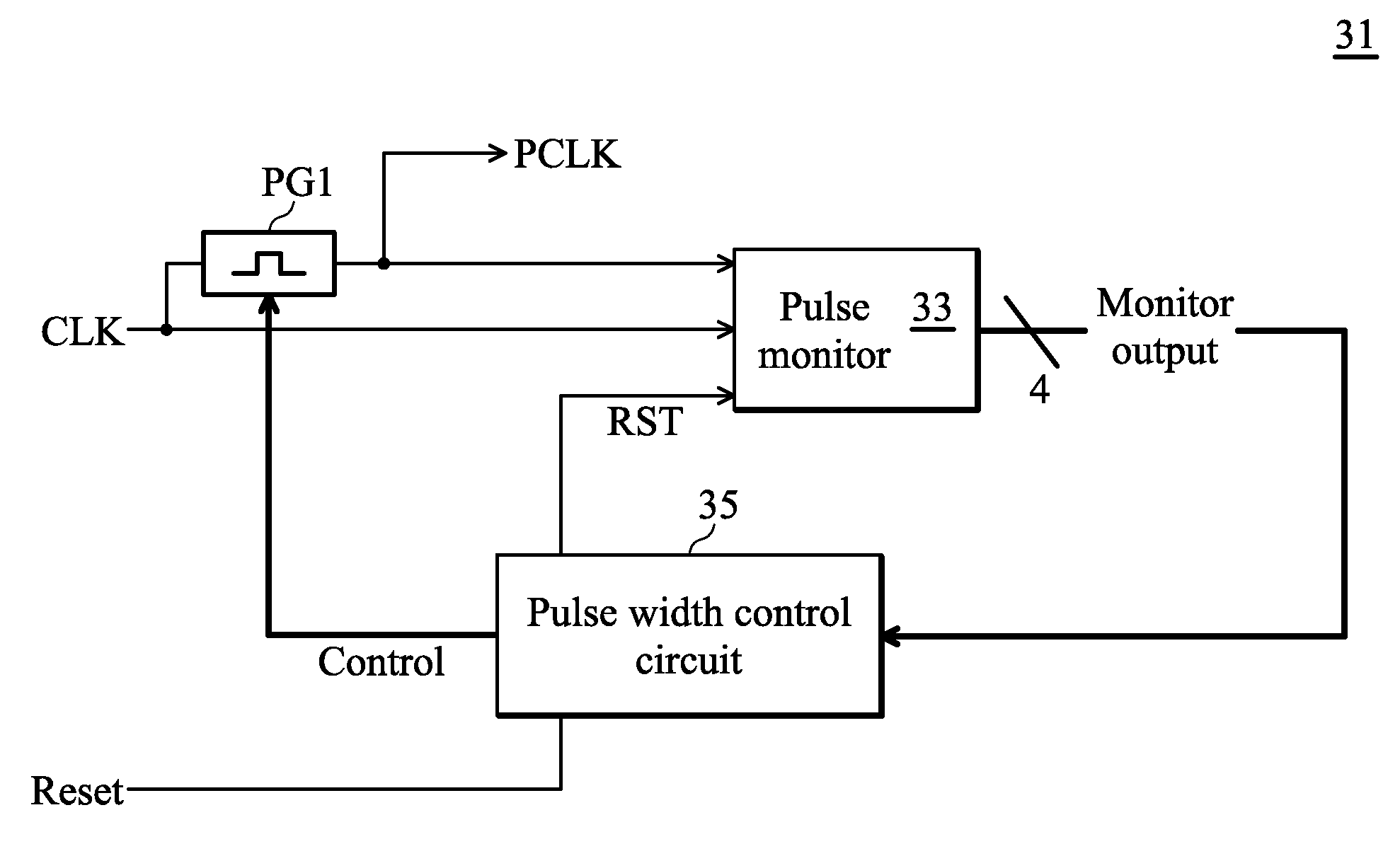
[0034]FIG. 3 depicts in one exemplary embodiment a block diagram of a pulse generator circuit 31 of the invention with a feedback control loop. In FIG. 3, a time varying CLK input signal is received. The input clock may be, in a typical application, a 50% duty cycle square wave signal. The variable pulse generator PG1 receives the clock input signal CLK and outputs a pulsed clock signal PCLK. The pulsed clock signal typically will have a shorter positive portion of its duty cycle, for example, 10-30%, and ranging up to 40% or so. The width of the pulse provided is controlled ...
PUM
 Abstract
Description
Claims
Application Information
 - R&D
- Intellectual Property
- Life Sciences
- Materials
- Tech Scout
- Unparalleled Data Quality
- Higher Quality Content
- 60% Fewer Hallucinations
Browse by: Latest US Patents, China's latest patents, Technical Efficacy Thesaurus, Application Domain, Technology Topic, Popular Technical Reports.
© 2025 PatSnap. All rights reserved.Legal|Privacy policy|Modern Slavery Act Transparency Statement|Sitemap|About US| Contact US: help@patsnap.com


