Touch sensor device and electronic apparatus having the same

Active Publication Date: 2010-10-14
NEC LCD TECH CORP
View PDF4 Cites 99 Cited by
  • Summary
  • Abstract
  • Description
  • Claims
  • Application Information

AI Technical Summary

Problems solved by technology

Note, however, that the items used for touching the sensor are limited to fingers and electrostatic conductive items forming a capacitance equivalent to the fingers.
In addition, it is necessary to pattern the conductive transparent layers for forming the transparent electrodes in a matrix form, which requires a large number of manufacturing steps.
In particular, indium that constitutes ITO is a rare metal, which is expensive.
Further, ITO is formed by vapor deposition, so that a long manufacturing tact time is required.
Thus, it is not possible to be mass-produced.
Therefore, ITO film makers cannot increase enough production of the films, and there is a short-supply of ITO films.
This resu

Method used


Image

  • Touch sensor device and electronic apparatus having the same
  • Touch sensor device and electronic apparatus having the same
  • Touch sensor device and electronic apparatus having the same

Examples


first exemplary embodiment

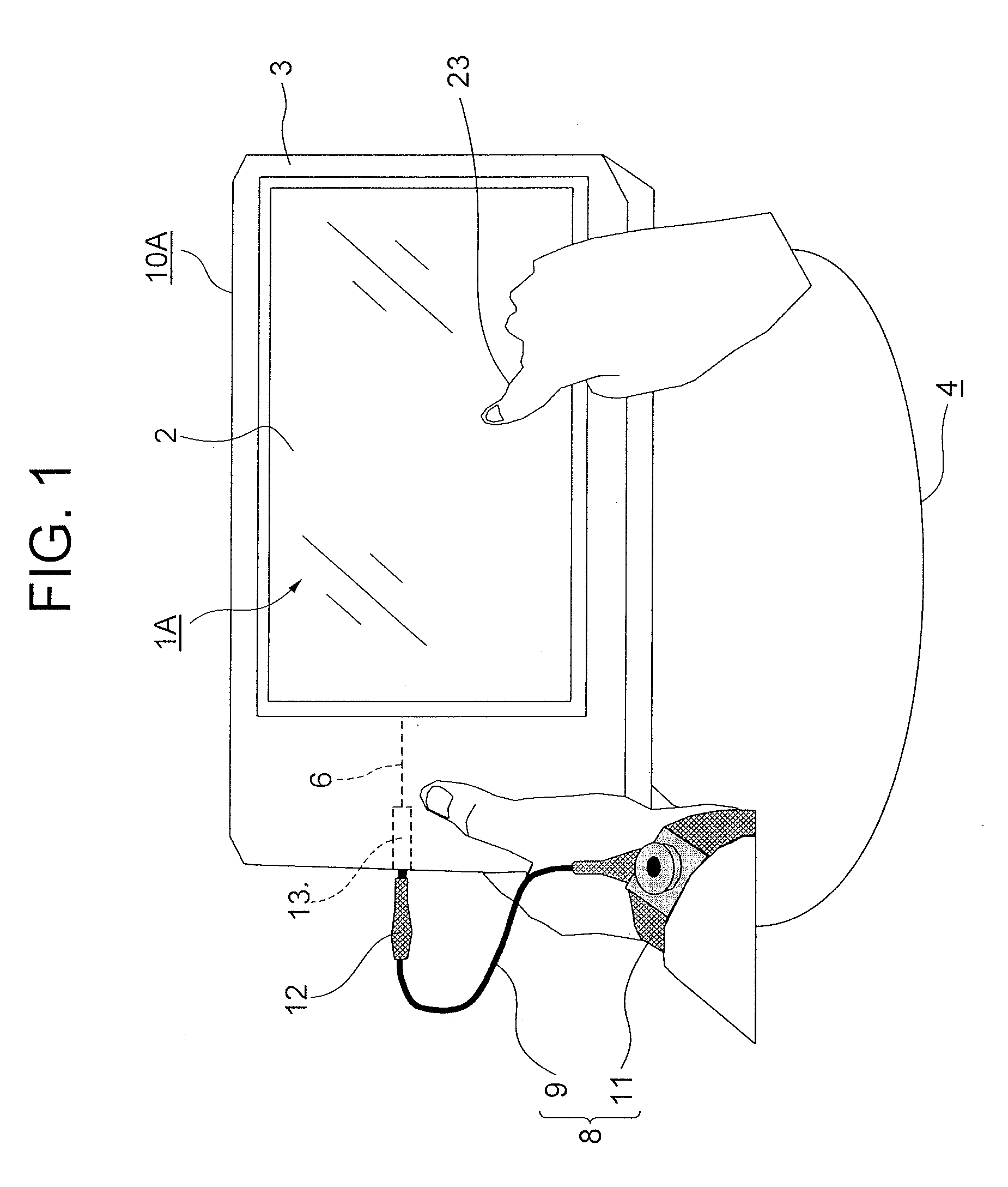
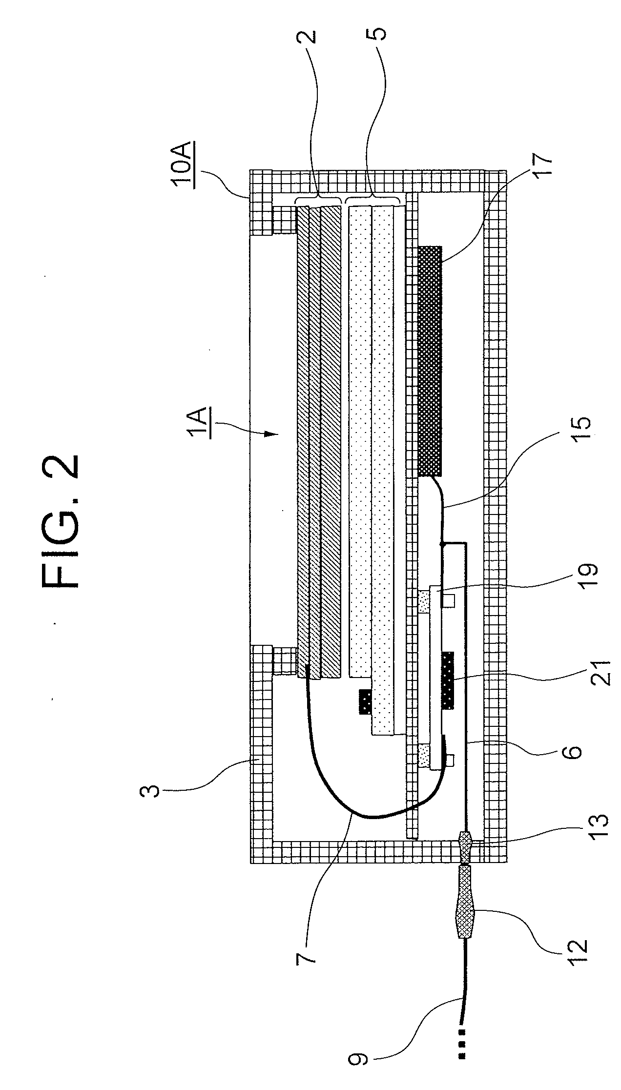
[0058]FIG. 1 is a perspective view showing a portable device to which a touch sensor device according to a first exemplary embodiment is loaded. FIG. 2 is a cross-sectional schematic view of the portable device shown in FIG. 1. FIG. 3 is an equivalent circuit diagram showing the touch sensor device of the first exemplary embodiment. Explanations will be provided hereinafter by referring to FIG. 1-FIG. 3.

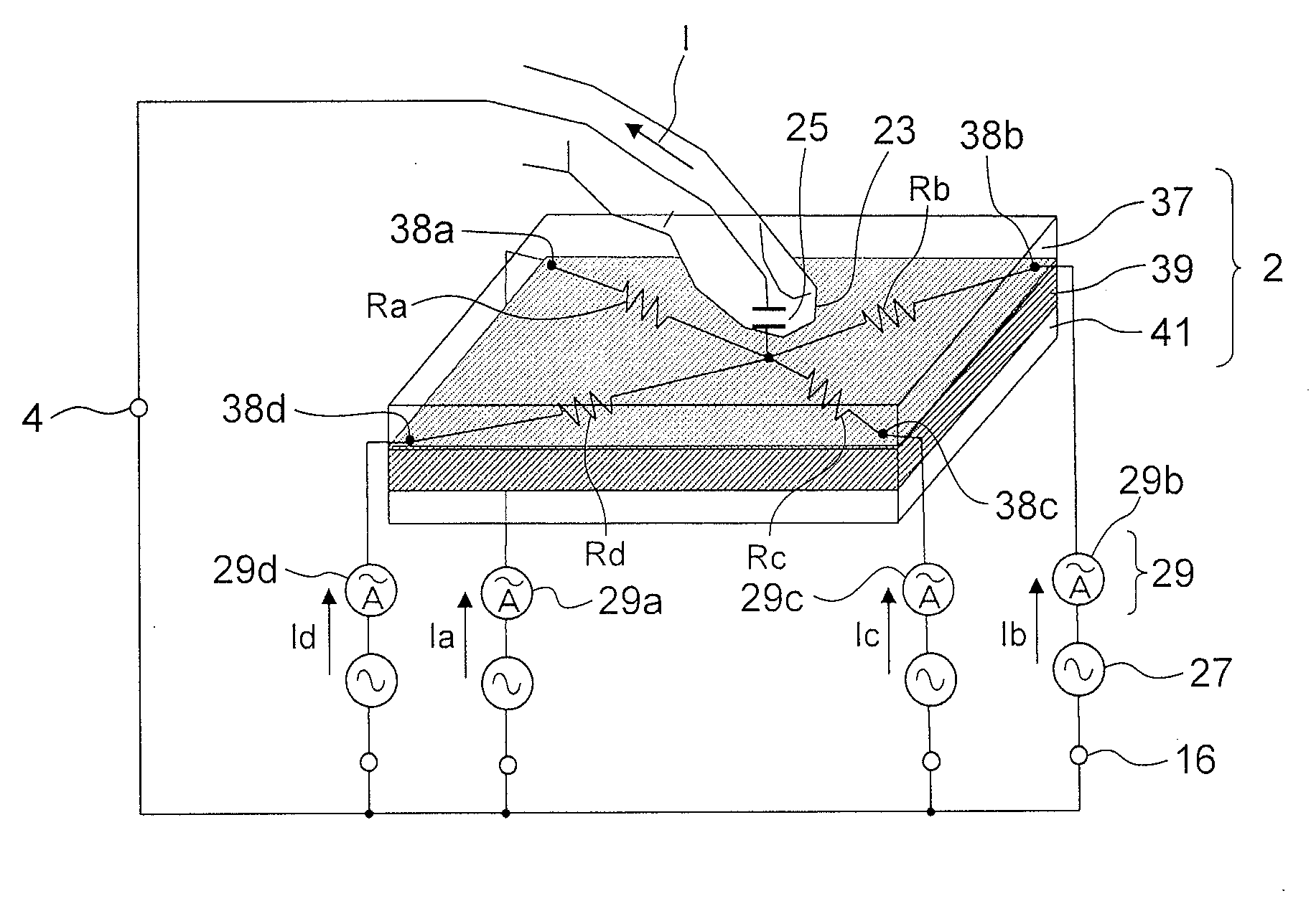
[0059]A touch sensor device 1A of the first exemplary embodiment includes: a first human body contact part (2) which forms a capacitance 25 between a human body 4 and itself when the human body 4 touches or approaches thereto; a power supply part (27) which outputs an AC voltage to the first human body contact part (2); a current detecting part (29) which detects electric currents flown from the power supply part (27) to the human body 4; reference potential parts (15, 16) which are the reference potentials of the AC voltage; and a second human body contact part 8 which is electrical...

second exemplary embodiment

[0114]Next, a second exemplary embodiment of the present invention will be described by referring to FIG. 8 and FIG. 9. Hereinafter, same reference numerals as those of the first exemplary embodiment are used for substantially the same structural elements as those of the first exemplary embodiment, and only different points from those of the first exemplary embodiment will be described. FIG. 8 is a perspective view showing a portable device to which a touch sensor device according to the second exemplary embodiment is loaded. FIG. 9 is a cross-sectional schematic view of the portable device shown in FIG. 8.

[0115]A touch sensor device 1B of the second exemplary embodiment is mounted into a portable device 10B. A second human body contact part is a conductor (3b) which forms the surface of a casing 3 of the portable device 10B. The conductor (3b) is achieved by a conducting part 3b of the casing 3.

[0116]In the first exemplary embodiment (FIG. 1 and FIG. 2) described above, the referen...

third exemplary embodiment

[0118]Next, a third exemplary embodiment of the present invention will be described by referring to FIG. 10. Hereinafter, same reference numerals as those of the second exemplary embodiment are used for substantially the same structural elements as those of the second exemplary embodiment, and only different points from those of the first exemplary embodiment will be described. FIG. 10A is a plan schematic view showing a portable device to which a touch sensor device according to the third exemplary embodiment is loaded, and FIG. 10B is a cross-sectional schematic view taken along a line I-I′ of FIG. 10A.

[0119]A touch sensor device 1C of the third exemplary embodiment is mounted into a portable device 10C. A second human body contact part is a conductor (3c) which forms the surface of a casing 3 of the portable device 10C. The conductor (3c) forms the entire surface of the casing 3 except the periphery of a first human body contact part (2) of the touch panel. The conductor (3c) is ...


PUM


Abstract

To provide a touch sensor device and the like, which can improve the detecting accuracy of a surface-capacitive type touch sensor. A touch sensor device of the present invention includes: a touch panel which forms a capacitance between a human body and itself when the human body makes a contact or approaches thereto; a power supply part which has a battery or the like which outputs a DC voltage, converts the DC voltage to an AC voltage, and outputs the AC voltage from the touch panel; a reference potential part to be a reference potential of the AC voltage; a wrist strap and a cable which are electrically connected to the reference potential part and to which the human body makes a contact; and a current detecting part which detects electric currents flown from the power supply part to the human body.

Description

CROSS-REFERENCE TO RELATED APPLICATIONS[0001]This application is based upon and claims the benefit of priority from Japanese patent application No. 2009-095957, filed on Apr. 10, 2009 and Japanese patent application No. 2010-049430, filed on Mar. 5, 2010, the disclosure of which is incorporated herein in its entirety by reference.BACKGROUND OF THE INVENTION[0002]1. Field of the Invention[0003]The present invention relates to a surface-capacitive type touch sensor device and an electronic apparatus and the like having the same.[0004]2. Description of the Related Art[0005]The touch sensor device is a device which detects coordinates of a position pointed by using a finger, a pen, or the like, or detects occurrence of pointing actions. Normally, it is used in combination with a surface display device such as a liquid crystal display (referred to as LCD hereinafter) or a plasma display panel (referred to as PDP hereinafter).[0006]A man-to-machine interface can be achieved by inputting a...

Claims


Application Information

Patent Timeline
IPC IPC(8): G06F3/045
CPCG02F1/13338G06F3/044G06F3/0416G06F3/04166G06F3/0444
Inventor YANASE, JIROHAGA, HIROSHI
Owner NEC LCD TECH CORP
Why Eureka
Try Eureka