
Method and Apparatus for Shielding Cooling Tubes in a Radiant Syngas Cooler

a technology of radiant syngas and cooling tubes, which is applied in the direction of indirect heat exchangers, combustible gas production, lighting and heating apparatus, etc., can solve the problems of heat exchangers exposed to hot syngas being damaged and even destroyed

Inactive Publication Date: 2010-10-21
GENERAL ELECTRIC CO
View PDF7 Cites 23 Cited by
  • Summary
  • Abstract
  • Description
  • Claims
  • Application Information

AI Technical Summary

Benefits of technology

"The invention is a system and method for cooling down a gasification process. The system includes a heat exchanger with coolant tubes and a heat shield to protect the cooling circuit from direct exposure to the hot gas. The method involves gasifying a feedstock, cooling the gas with the heat exchanger, and transmitting it to a syngas cooler. The technical effect is to improve the efficiency and safety of the gasification process by reducing the temperature of the gas before it reaches the syngas cooler."

Problems solved by technology

However, heat exchangers exposed to the hot syngas may be damaged, and even destroyed due to exposure to the hot syngas.

Method used


Image

  • Method and Apparatus for Shielding Cooling Tubes in a Radiant Syngas Cooler
  • Method and Apparatus for Shielding Cooling Tubes in a Radiant Syngas Cooler
  • Method and Apparatus for Shielding Cooling Tubes in a Radiant Syngas Cooler

Examples


Embodiment Construction

[0014]One or more specific embodiments of the present invention will be described below. In an effort to provide a concise description of these embodiments, all features of an actual implementation may not be described in the specification. It should be appreciated that in the development of any such actual implementation, as in any engineering or design project, numerous implementation-specific decisions must be made to achieve the developers' specific goals, such as compliance with system-related and business-related constraints, which may vary from one implementation to another. Moreover, it should be appreciated that such a development effort might be complex and time consuming, but would nevertheless be a routine undertaking of design, fabrication, and manufacture for those of ordinary skill having the benefit of this disclosure.

[0015]When introducing elements of various embodiments of the present invention, the articles “a,”“an,”“the,” and “said” are intended to mean that ther...


PUM

PropertyMeasurementUnit
pressuresaaaaaaaaaa
temperaturesaaaaaaaaaa

Abstract

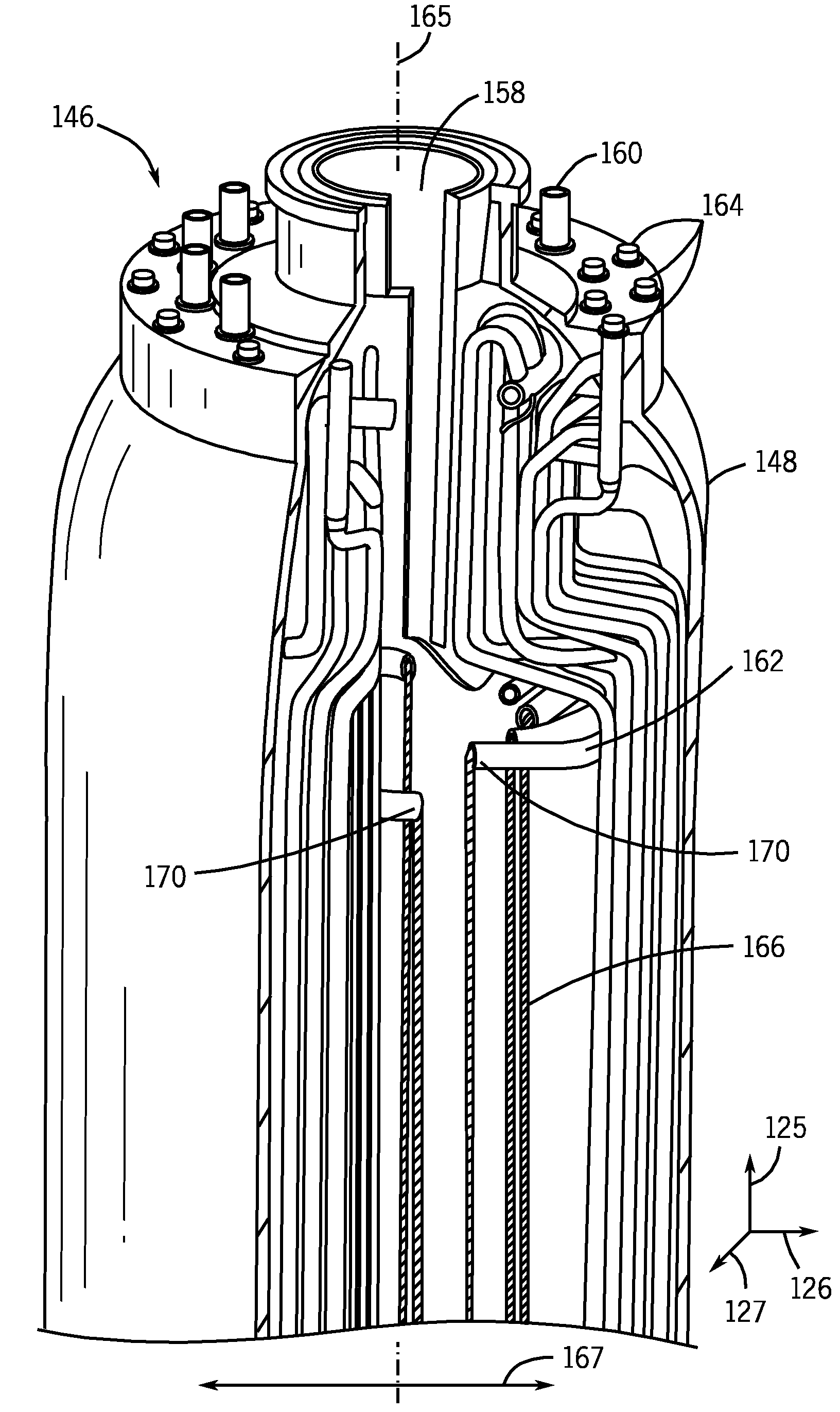
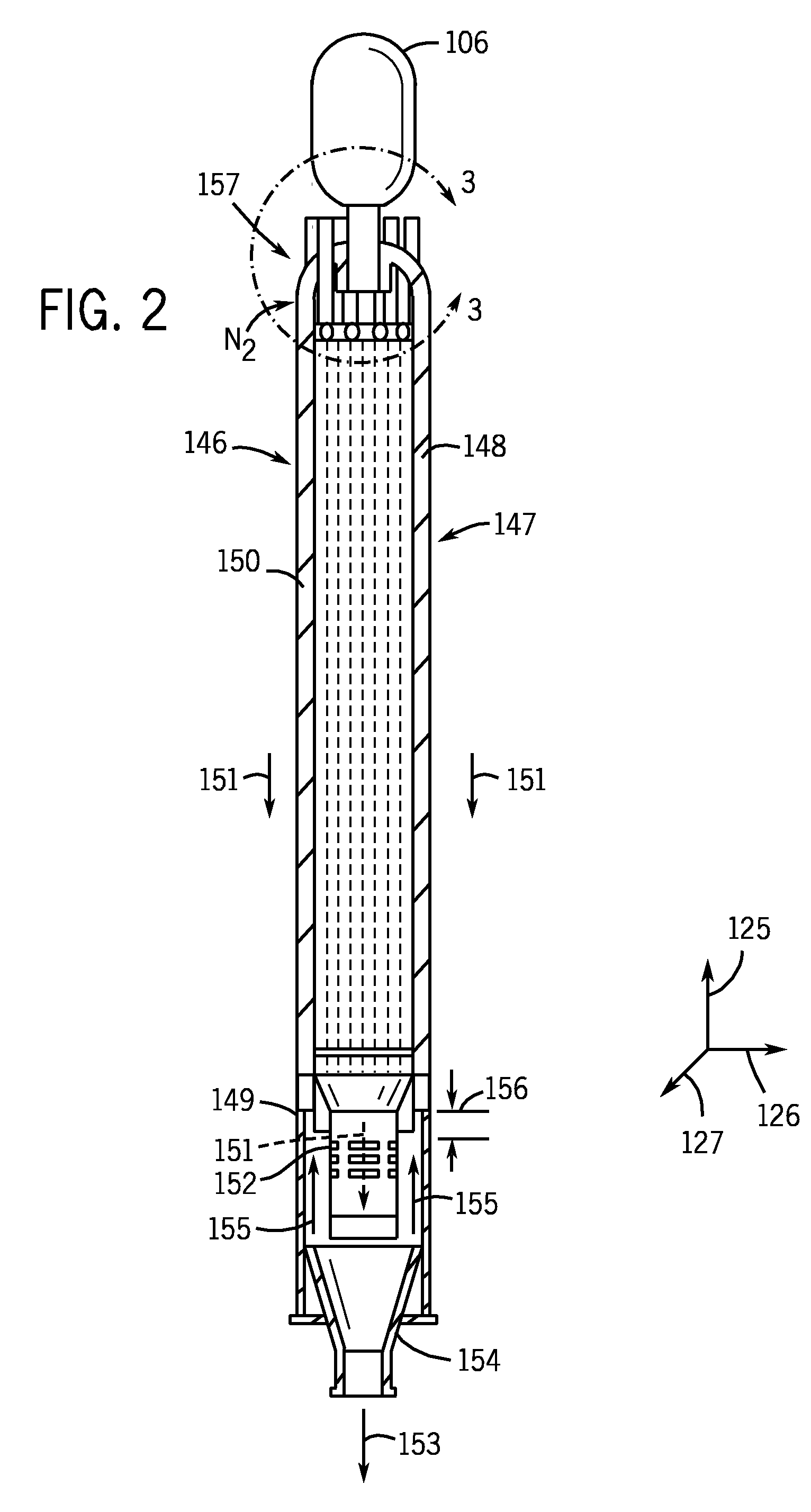
Methods and a system for shielding cooling tubes in a radiant syngas cooler. The heat shields may prevent direct contact between heated syngas and the cooling tubes. The heat shield may be mounted to a header that also attaches to the cooling tubes. The heat shield may also be separated from the cooling tubes or, alternatively, the heat shield may be coated onto the cooling tubes. Furthermore, prolonged exposure to the heated syngas may corrode the heat shield.

Description

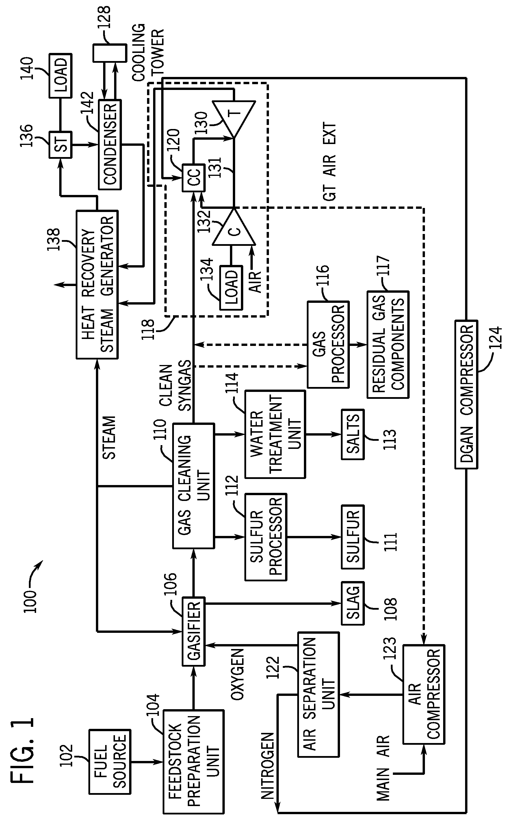
BACKGROUND OF THE INVENTION[0001]The subject matter disclosed herein relates to a heat shield for use with a radiant syngas cooler.[0002]In general, integrated gasification combined cycle (IGCC) power plants are capable of generating energy from various hydrocarbon feedstock, such as coal, relatively cleanly and efficiently. IGCC technology may convert the hydrocarbon feedstock into a gas mixture of carbon monoxide (CO) and hydrogen (H2), i.e., syngas, by reaction with steam in a gasifier. These gases may be cleaned, processed, and utilized as fuel in a conventional combined cycle power plant. For example, the syngas may be fed into a combustor of a gas turbine of the IGCC power plant and ignited to power the gas turbine for use in the generation of electricity. Coal gasification processes may utilize compressed air or oxygen to react with the coal to form the CO and H2. These processes may take place at relatively high pressures and temperatures and may be more efficient at design ...

Claims


Application Information

Patent Timeline
Patent Type & Authority Applications(United States)
IPC IPC(8): F28F13/18F28D7/00
CPCC10J3/86F28D7/1669F28D2021/0075F28F19/002F28F19/02Y02E20/18F28F9/00C10K1/003C10K1/004C10J2300/165C10J2300/1675C10J2300/169Y02E20/16C10K1/006
Inventor CORRY, JUDETH BRANNONSTOREY, JAMES MICHAEL
Owner GENERAL ELECTRIC CO
Learn More