Inlet Swirl Control for Turbochargers

Active Publication Date: 2010-10-21
FORD GLOBAL TECH LLC
View PDF5 Cites 15 Cited by
  • Summary
  • Abstract
  • Description
  • Claims
  • Application Information

AI Technical Summary

Benefits of technology

[0002]Airflow characteristics at an inlet compressor inlet may affect turbo inlet efficiency and reduce turbulence related noise by providing additional margin to the compressor surge line. Specifically, the direction of swirl relative to the compressor rotation direction can affect both efficiency and noise. If the swirl direction is opposite from the compressor, turbulence and noise can result, sometimes referred to as tip-in whoosh. Inducing a swirl in the same direction as the compressor can result in improved inlet efficiency (higher mass flow rate) and reduced noise generation.
[0003]U.S. Pat. No. 7,322,191 discloses a device for imparting a whirling motion on the flow of air for supplying a turbo-supercharged internal-combustion engine. The device is designed to be interposed upstream from the elbow of an elbow-shaped duct. The duct supplies air to the supercharger. The duct has an upstream branch having a square, or rectangular, cross-section, and a downstream branch having a circular section to facilitate formation of a helical flow through the downstream branch. A vane is mounted oscillating about an axis in the upstream branch. In this way, the downstream branch of the elb

Problems solved by technology

Specifically, the direction of swirl relative to the compres

Method used


Image

  • Inlet Swirl Control for Turbochargers
  • Inlet Swirl Control for Turbochargers
  • Inlet Swirl Control for Turbochargers

Examples


Example

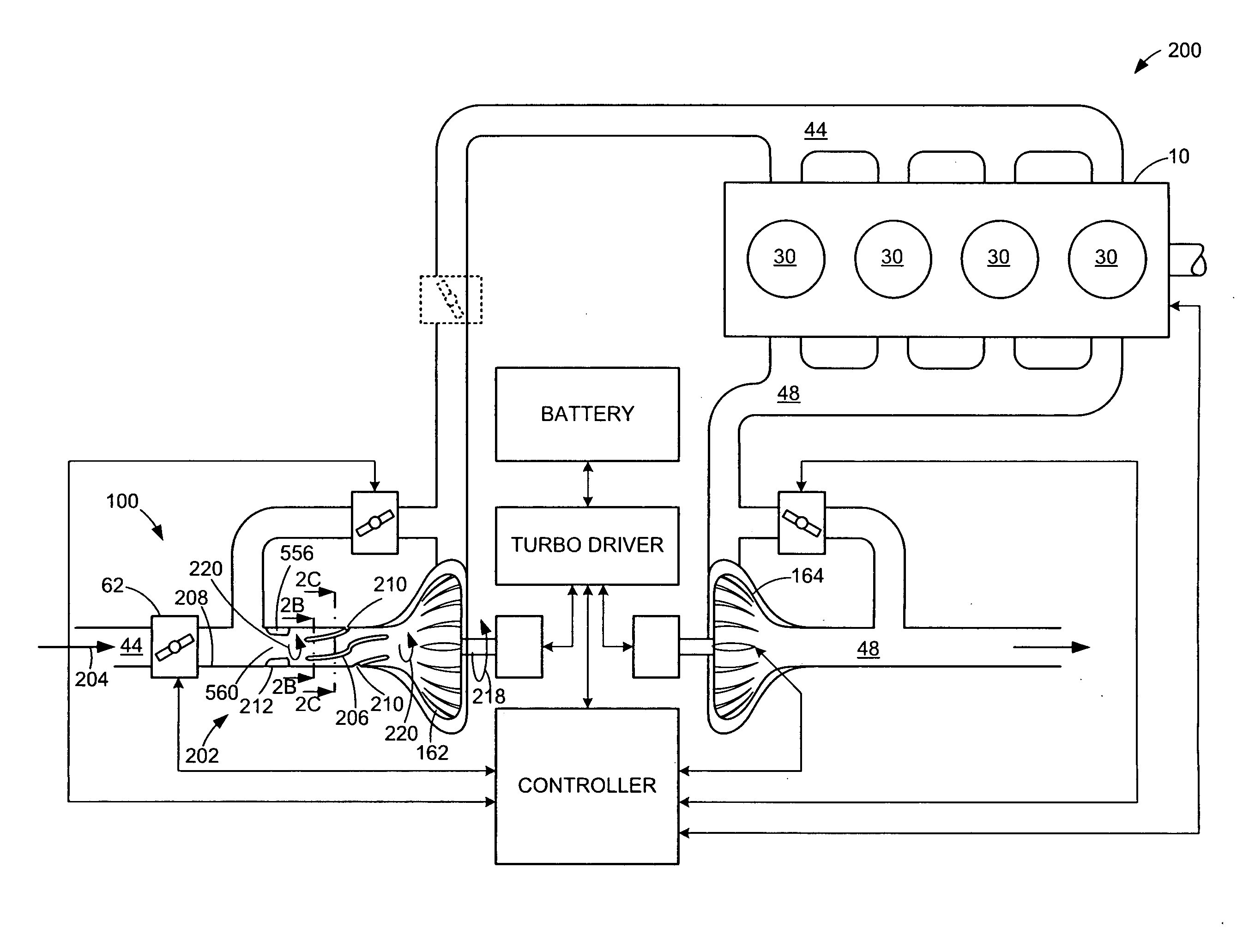
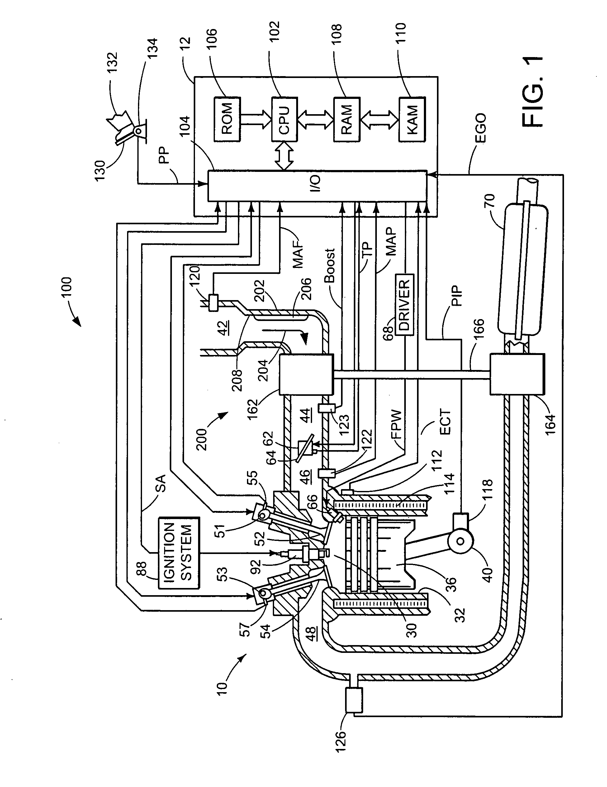
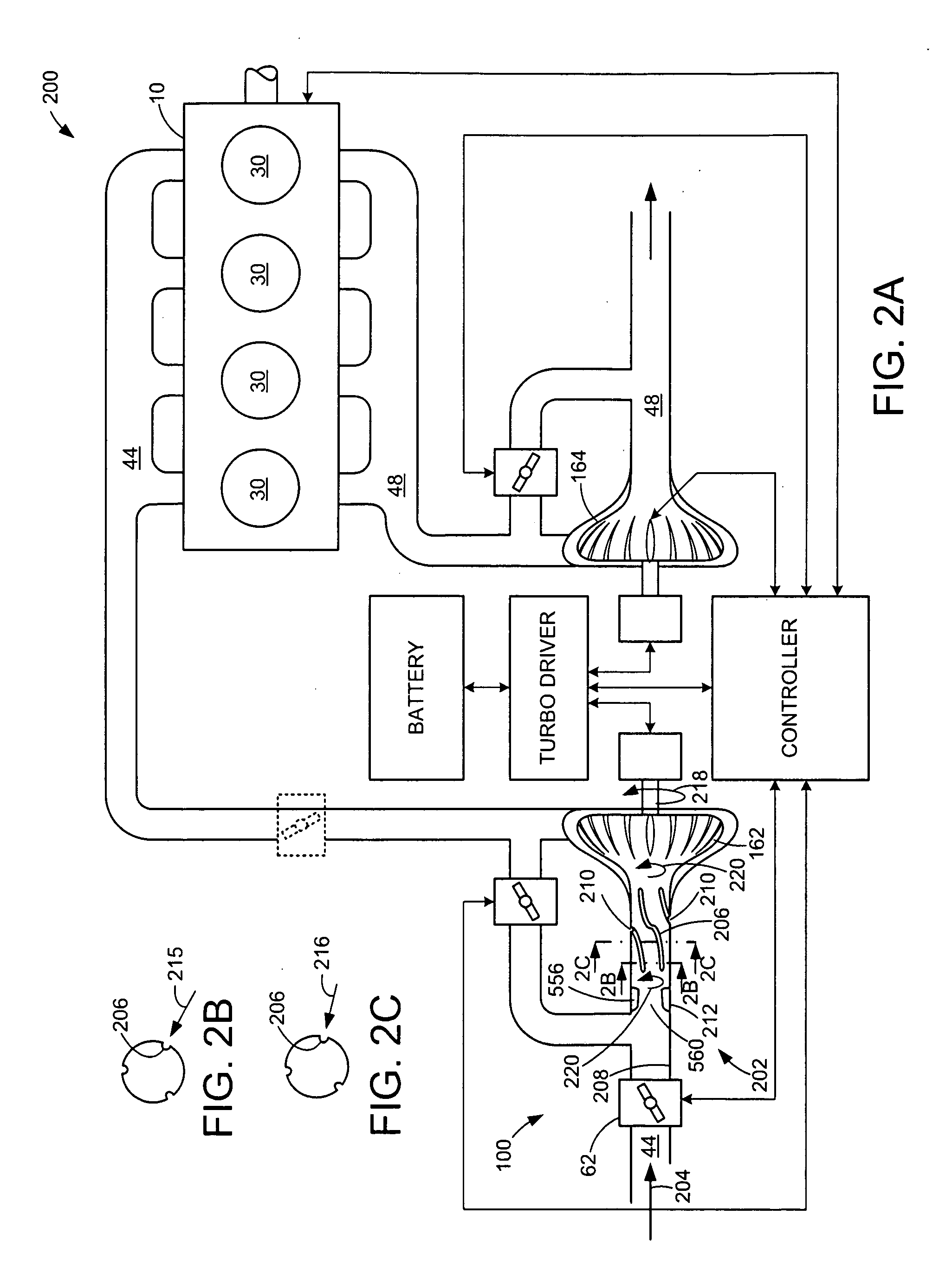
[0019]FIG. 1 is a schematic diagram showing one cylinder of multi-cylinder engine 10, which may be included in a propulsion system of an automobile. Engine 10 may be controlled at least partially by a control system including controller 12, and by input from a vehicle operator 132 via an input device 130. In this example, input device 130 includes an accelerator pedal and a pedal position sensor 134 for generating a proportional pedal position signal PP. Combustion chamber (i.e., cylinder) 30 of engine 10 may include combustion chamber walls 32 with piston 36 positioned therein. Piston 36 may be coupled to crankshaft 40 so that reciprocating motion of the piston is translated into rotational motion of the crankshaft. Crankshaft 40 may be coupled to at least one drive wheel of a vehicle via an intermediate transmission system. Further, a starter motor may be coupled to crankshaft 40 via a flywheel to enable a starting operation of engine 10.

[0020]Combustion chamber 30 may receive int...


PUM


Abstract

An inlet duct, an induction system, and a system are disclosed for directing an inlet flow into an inlet compressor for use in an internal combustion engine. An example inlet duct may include one or more relief features disposed on an inner surface of the inlet duct. The one or more relief features may be made integral with the inlet duct. The one or more relief features may be disposed to protrude into the inlet flow to cause the inlet flow to swirl before reaching the inlet compressor.

Description

BACKGROUND AND SUMMARY [0001]Turbochargers, and superchargers, may be used with internal combustion engines to increase the mass of air entering the combustion chamber of the engine to create more power. An inlet compressor in the form of, for example, a radial fan pump may be disposed in an inlet duct to compress inlet air. In some cases the inlet compressor may be driven by the energy of the exhaust gases of the engine.[0002]Airflow characteristics at an inlet compressor inlet may affect turbo inlet efficiency and reduce turbulence related noise by providing additional margin to the compressor surge line. Specifically, the direction of swirl relative to the compressor rotation direction can affect both efficiency and noise. If the swirl direction is opposite from the compressor, turbulence and noise can result, sometimes referred to as tip-in whoosh. Inducing a swirl in the same direction as the compressor can result in improved inlet efficiency (higher mass flow rate) and reduced...

Claims


Application Information

Patent Timeline
IPC IPC(8): F01D9/00F02B33/00
CPCF02B37/00F04D29/44F02B37/16F02B37/18F02M29/06Y02T10/14F02M35/10163F02M35/10262Y02T10/146Y02T10/144F02M35/10019Y02T10/12Y10T137/2087
Inventor HERMANN, ERIC HENRYSTEC, RANDALL ALANWHITE, DOUGLASTOMLIN, JACQUELINERONZI, WILLIAM C.KHAMI, ROGERBONHARD, ROBERT BRUCEBODDAKAYALA, BHASKARA RAO
Owner FORD GLOBAL TECH LLC
Why Eureka
Try Eureka