
Charging roll and method of producing the same

Inactive Publication Date: 2010-10-21
TOKAI RUBBER IND LTD
View PDF36 Cites 9 Cited by
  • Summary
  • Abstract
  • Description
  • Claims
  • Application Information

AI Technical Summary

Benefits of technology

[0012]The present invention has been made in the light of the situation described above. It is therefore an object of the invention to provide a charging roll that prevents a printed or reproduced image from suffering from defects even when the charging roll is used for a long period of time and prevents a surface layer from separating when an electrophotographic machine is operated after the charging roll is left under high temperature and humidity conditions while being installed in an electrophotographic machine. It is another object of the present invention to provide a method of producing such a charging roll.
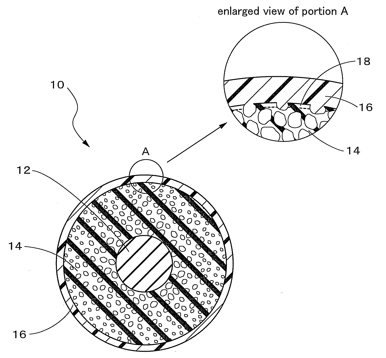
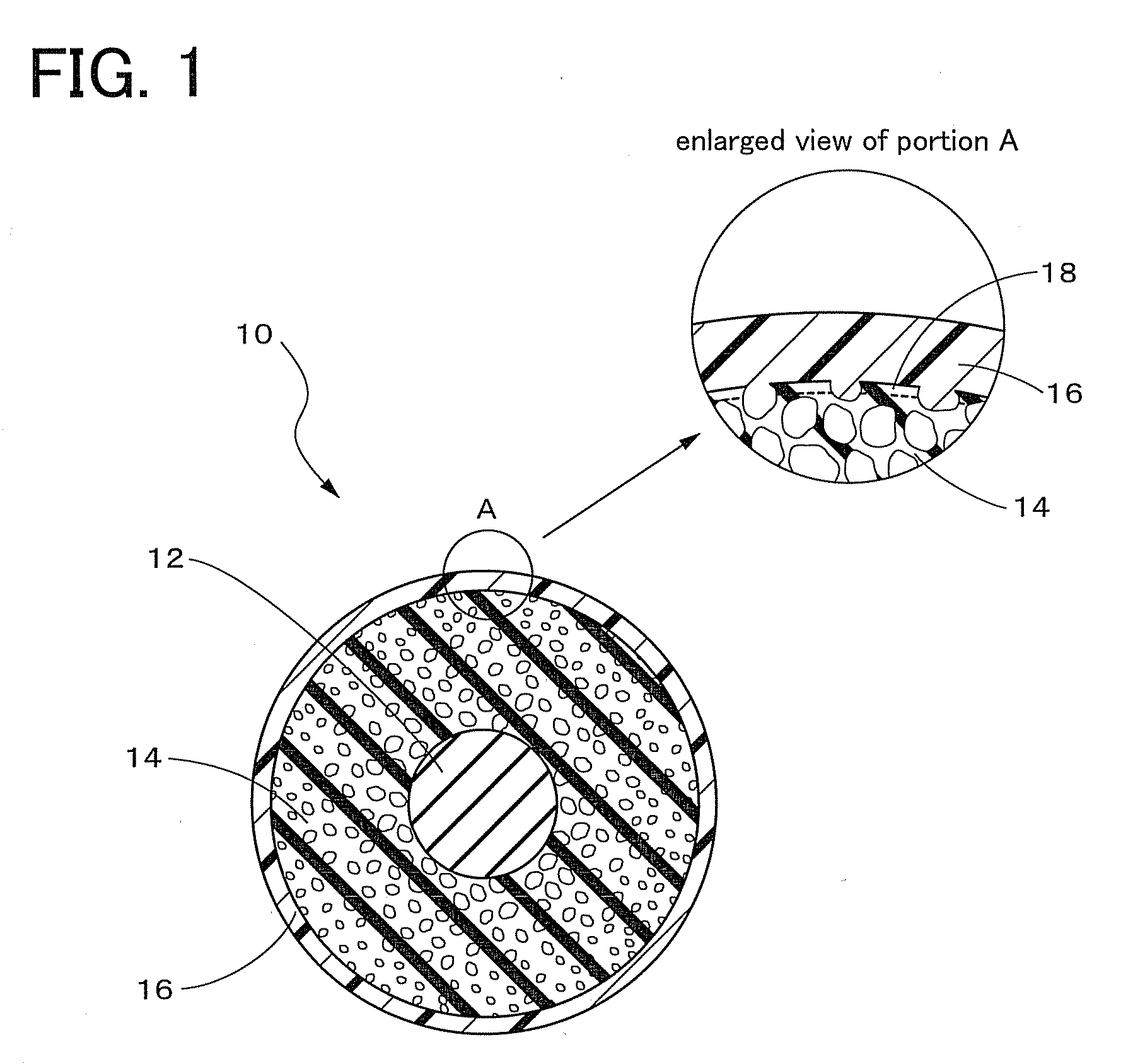
[0017]As described above, the surface layer as an outermost layer of the charging roll according to the present invention is formed of the synthetic resin composition mainly composed of a synthetic resin material having a glass transition temperature of from 0 to 45° C., so that hardness thereof is relatively low. Accordingly, even when toner remain on a surface of the image-bearing medium such as a photosensitive drum due to a long period of use, load to be applied to the toner is effectively reduced. As a result, generation of stain caused by the adhesion of toner on the charging roll surface can be advantageously prevented, thus defects of the printed image can be effectively prevented.
[0018]Further, the surface layer of the charging roll according to the present invention is formed radially outwardly of the electrically conductive rubber foam layer which includes, at a superficial layer thereof, the skin layer having an opening area ratio of from 0.5 to 20%, so that an area of contact between the surface layer and the electrically conductive rubber foam layer is sufficiently secured. As a result, even when the electrophotographic machine is operated after the charging roll of the present invention is left under high temperature and humidity conditions while being installed in the electrophotographic machine (cartridge), the surface layer of the charging roll can be prevented from separating.
[0019]Further, according to the method of producing the charging roll of the present invention, the charging roll having the above-described characteristics can be advantageously produced.

Problems solved by technology

However, when the surface layer of the charging roll having the above structure is formed of a synthetic resin composition (formation material of a surface layer) including a hard synthetic resin material (a synthetic resin material having a high glass transition temperature) as a main component, the charging roll to be obtained suffers from the following problems due to the high hardness of the charging roll.
Therefore, when the charging roll is used for a long period of time, toner is adhered to the surface of the charging roll and undesirable lines appear on the surface of the charging roll in a circumferential direction thereof.
Due to the lines appeared on the surface of the charging roll, quality of the image to be printed is undesirably deteriorated.
The cartridges including the above-described charging rolls also have the above-described problems.

Method used


Image

  • Charging roll and method of producing the same
  • Charging roll and method of producing the same

Examples


examples

[0046]To further clarify the principle of the present invention, several examples of the present invention will be described below. However, it is to be understood that the invention is by no means limited to the details of these examples, but may be embodied with various changes, modifications and improvements which may occur to those skilled in the art, without departing from the scope of the present invention.

[0047]Initially, five kinds of foamable conductive rubber compositions (A to E) were prepared, so as to have the respective compositions as indicated in the following Table 1. In the preparation of each composition, the following rubber material and agents are used.

[0048]Epichlorohydrin rubber: EPICHLOMER CG102 (product name), available from DAISO CO., LTD.

[0049]Quaternary ammonium salt: tetramethylammonium perchlorate

[0050]Zinc oxide: zinc oxide type 2 (product name), available from Sakai Chemical INDUSTRY Co., Ltd.

[0051]Azodicarbonamide: cellmic RUB (product name), availab...


PUM


Abstract

A charging roll is provided which does not cause image defects even when being used for a long period of time and does not allow a surface layer to be separated when an electrophotographic machine is operated after the charging roll installed therein is left under high temperature and humidity conditions. A charging roll includes a shaft, an electrically conductive rubber foam layer formed on an outer circumferential surface of the shaft, and a surface layer formed radially outwardly of the electrically conductive rubber foam layer. The electrically conductive rubber foam layer includes a skin layer having an opening area ratio of from 0.5 to 20% at a superficial layer of the electrically conductive rubber foam layer, and the surface layer is formed of a synthetic resin composition mainly composed of a synthetic resin material having a glass transition temperature of from 0 to 45° C.

Description

[0001]The present application is based on Japanese Patent Application Nos. 2009-098858 and 2009-293761 filed on Apr. 15, 2009 and Dec. 25, 2009, respectively, the contents of which are incorporated herein by reference.BACKGROUND OF THE INVENTION[0002]1. Field of the Invention[0003]The present invention relates to a charging roll for use in an image forming apparatus such as an electrophotographic copier, printer, or facsimile machine. In particular, the invention is concerned with such a charging roll for charging an image-bearing medium such as a photoconductive or photosensitive medium used in electrophotography, and a dielectric medium used in electrostatic recording.[0004]2. Description of the Related Art[0005]In an image forming apparatus (hereinafter, referred to as an electrophotographic machine) such as an electrophotographic copier, printer, or facsimile machine, a so-called roll charging method has been widely adopted, in which a charging roll and an image-bearing medium s...

Claims


Application Information

Patent Timeline
IPC IPC(8): B05C1/08B05D5/12G03G15/02
CPCG03G15/0233
Inventor KASHIHARA, SHINKICHIKAWANO, ATSUHIROSAITO, YOSHIHIRO
Owner TOKAI RUBBER IND LTD
Learn More