Microfluidic oscillating tube densitometer for downhole applications

a microfluidic oscillating tube and densitometer technology, which is applied in the direction of vibration measurement in solids, fluid pressure measurement by mechanical elements, special data processing applications, etc., can solve the problem of reducing the sensor's sensitivity to fluid density, adding to the complexity of the device, and unable to obtain large quantities of representative downhole fluids. problem, to achieve the effect of accurate reporting of fluid density

Active Publication Date: 2010-10-21
SCHLUMBERGER TECH CORP
View PDF40 Cites 43 Cited by
  • Summary
  • Abstract
  • Description
  • Claims
  • Application Information

AI Technical Summary

Benefits of technology

[0036]Another advantage of at least one embodiment of the invention is that the invention is capable of minimizing the amount of pumped fluid necessary for the densitometer to accurately report the fluid density.

Problems solved by technology

A further challenge in downhole fluid analysis is that it is a challenge to obtain large quantities of representative downhole fluids due to the ever-present contamination, whether drilling mud or formation water [O. C. Mullins, M. Hashem, H. Elshahawi, G. Fujisawa, C. Dong, S. Betancourt, T. Terabayashi, Petrophysics 46, 302 (2005)].
Adding the mass of such transducers decreases the sensor's sensitivity to fluid density as well as adding to the complexity of the device.
The problem with trying to obtain a density measurement outside of a laboratory / controlled environment is that the density of most fluids varies with temperature.
Thus, controlling the temperature of stored calibration fluid along with ensuring the temperature of the fluid does not change while the fluid is being pumping to the measuring device, can be both expensive and a difficult process.
However, the above reference has many drawbacks, such as a geometry that requires a large quantity of fluid in order to completely replace a fluid that is initially present in the tube with a second one.
Furthermore, it has an internal volume closer to milliliters rather than microliters, and a geometry that it is not optimized to operate at large pressures.
The SPARKS device is unable to operate at pressures much above ambient pressures as the vibrating element consists of a thin-walled silicon tube.
Moreover, the SPARKs device is not a device operable downhole and is limited to low pressure and low temperature.
However, the main drawback for the Pelletier device, among other things, is that it requires milliliter-sized volumes as fluid for operation, predominantly discusses measurements with respect to a second tube referred to as a standard, along with being disclosed as a large device.
Further, another major drawback of the PELLETIER '364 reference is that it is impractical as well as not commercially viable due to the use of the reference frequency originating from the idea that there will be a second vibrating tube in the tool, filled with a fluid of known properties or a vacuum.
The PELLETIER '281 has other drawbacks, as mentioned above, utilizes milliliter scale volumes of fluid for operation and requires either the excitation or detection components to be clamped to the tube, thereby decreasing the sensor's sensitivity.
However, the sensor device of PERMUY requires several milliliters of fluid at a minimum.
However, this device requires milliliters of fluid to measure density.
Further, the Anton Paar reference requires milliliter scale volumes of fluid for operation which is not suitable for below ground environments.
However, there are many drawback to this device since, first there is no disclosed pressure housing, and secondly, the disclosed device would suffer from electrical issues since no electrical isolators or similar like devices have been incorporated.

Method used


Image

  • Microfluidic oscillating tube densitometer for downhole applications
  • Microfluidic oscillating tube densitometer for downhole applications
  • Microfluidic oscillating tube densitometer for downhole applications

Examples


Embodiment Construction

[0046]The particulars shown herein are by way of example and for purposes of illustrative discussion of the embodiments of the present invention only and are presented in the cause of providing what is believed to be the most useful and readily understood description of the principles and conceptual aspects of the present invention. In this regard, no attempt is made to show structural details of the present invention in more detail than is necessary for the fundamental understanding of the present invention, the description taken with the drawings making apparent to those skilled in the art how the several forms of the present invention may be embodied in practice. Further, like reference numbers and designations in the various drawings indicated like elements.

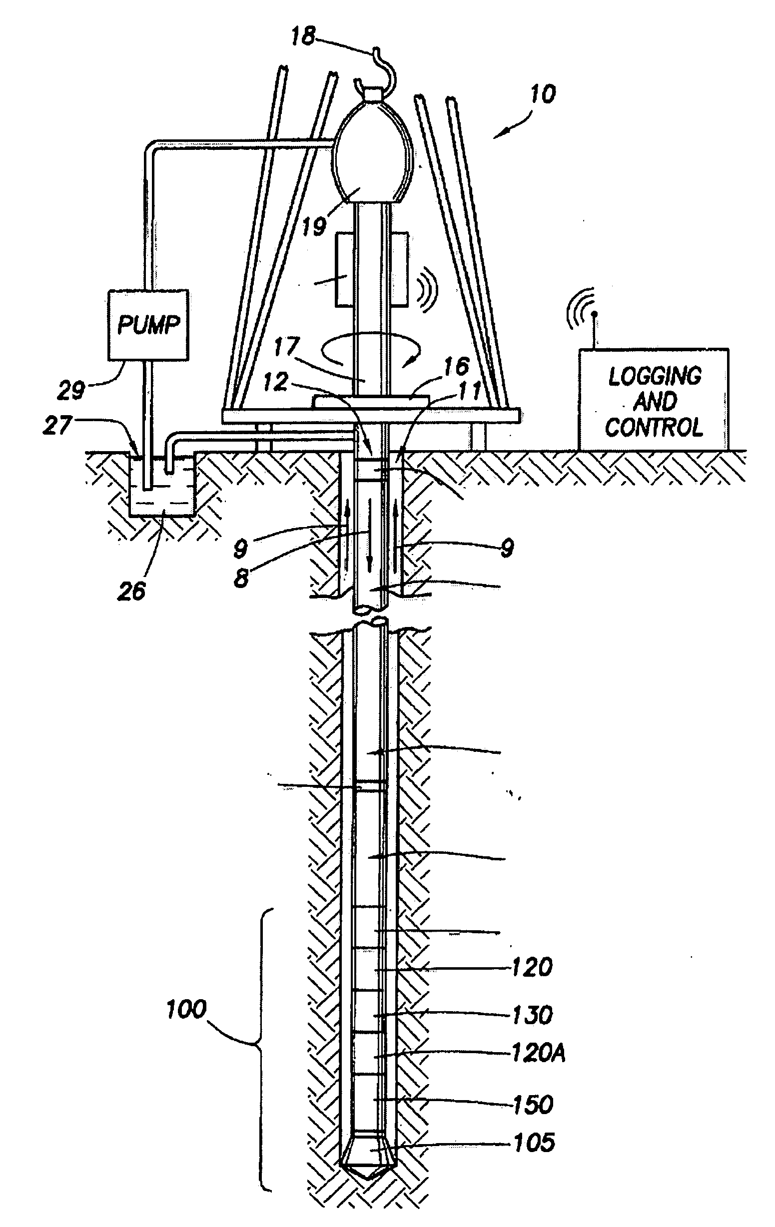
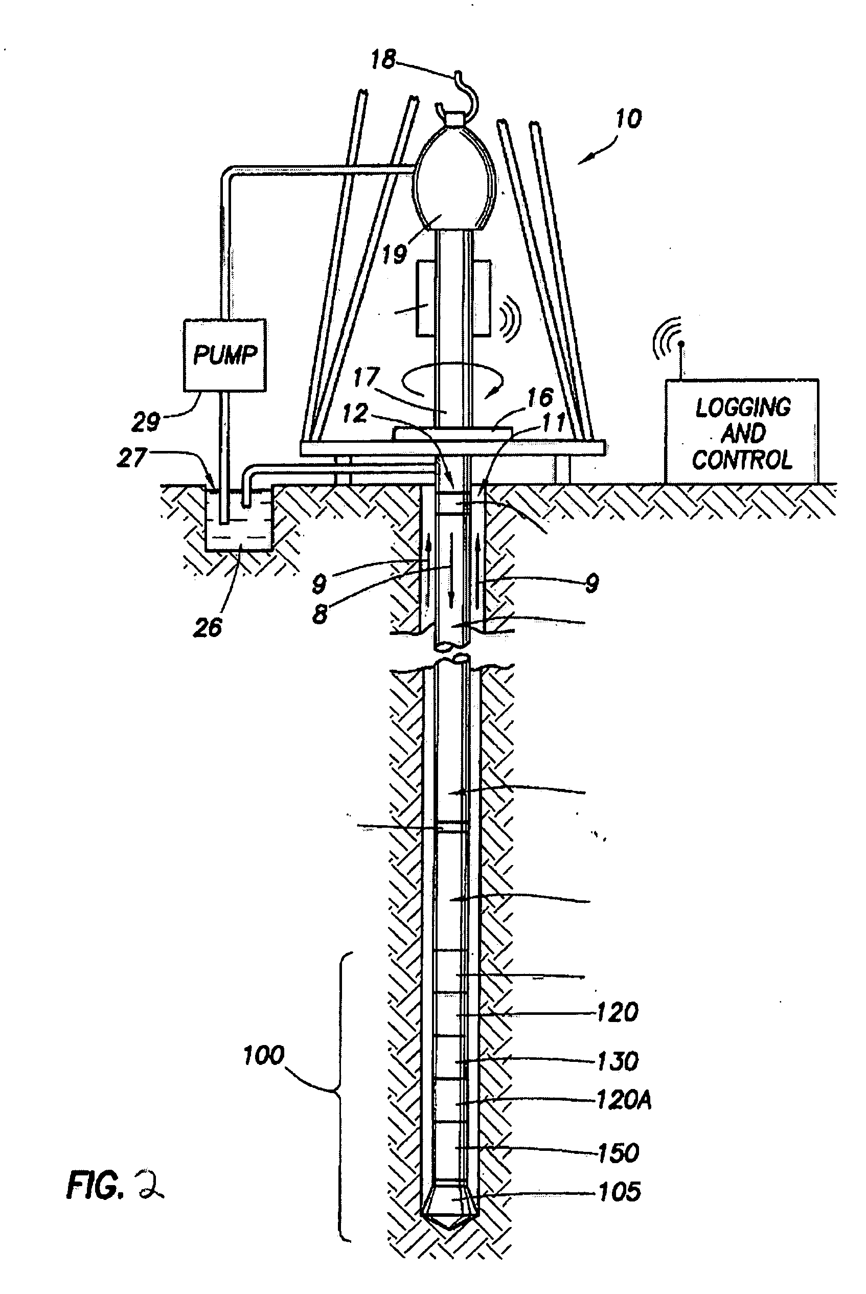
[0047]According to embodiment of the invention, the invention includes a device for determining one or more properties of at least one fluid sample. The device includes a tube configured to receive the at least one fluid samp...


PUM

PropertyMeasurementUnit
volumeaaaaaaaaaa
pressuresaaaaaaaaaa
voltageaaaaaaaaaa

Abstract

Devices, methods and systems for determining one or more properties of at least one fluid sample. A tube configured to receive the at least one fluid sample wherein the tube is placed in a pressure housing. Further, an excitation source configured to generate vibration of the tube whereby a circulation of an electrical current along a portion of the tube is subjected to at least one magnetic field produced by at least one magnet. Further still, at least one vibration sensor that converts vibrations of the tube into a measurement signal. Finally, a processor that receives the measurement signal determines a resonant frequency from the measurement signal using a frequency measuring device to determine a property of the one or more properties of the at least one sample fluid.

Description

BACKGROUND OF THE INVENTION[0001]1. Field of the Invention[0002]The present invention generally relates to devices and methods for measuring fluid properties for oilfield applications and other industries, e.g., chemical and food industries. In particular, the invention relates to the measurement of the density of microfluidic volumes of fluids for surface and downhole oilfield applications.[0003]2. Background of the Invention[0004]Understanding fluid density and other fluid properties downhole is paramount to petroleum exploration as it enables one to differentiate between oil, gas and water [W. D. McCain, Jr., The Properties of Petroleum Fluids, 2nd ed. (1990)]. Furthermore, it allows one to locate the oil-water contact line and hence the thickness of the pay zone of a formation. As a consequence, it is a must that robust sensors be developed that can accurately measure fluid density and other fluid properties in a harsh environment found in an oilwell. Oilfield pressures downhole...

Claims


Application Information

Patent Timeline
Patent Type & Authority Applications(United States)
IPC IPC(8): G01V1/40G01N29/036G01L7/00G01K1/00
CPCG01N9/002E21B49/08G01N27/74G01N29/02E21B49/0875
Inventor HARRISON, CHRISTOPHERCOLEOU, CHLOEGRANT, BILLJUNDT, JACQUES
Owner SCHLUMBERGER TECH CORP
Why Eureka
Try Eureka