
Optical passive network system and its operation method

a network system and optical passive technology, applied in the field of optical passive network system configuration, can solve the problems of increasing the cost of new optical fiber installation, limiting the performance of existing pon, and increasing the number of child stations. the effect of cost, increasing the number of child stations, and prolonging the communication distan

Inactive Publication Date: 2010-10-28
HITACHI LTD
View PDF4 Cites 27 Cited by
  • Summary
  • Abstract
  • Description
  • Claims
  • Application Information

AI Technical Summary

Benefits of technology

[0014]Since burst signals from the child stations are converted into a continuous optical signal to be transmitted to the parent station, burst signals from the child stations having different optical intensities are converted into a continuous optical signal having a constant intensity to reach the parent station. An up signal receiver of the parent station can therefore be made of components of simple structures, resulting in simplification and low cost.
[0015]Even in the case wherein a relay is introduced into an optical communication system (PON) to prolong a communication distance between the parent station and child station and to increase the number of accommodated child stations, the relay reproduces the up signals to form a continuous signal. It is therefore possible to reduce the bandwidth to be assigned to a guard band between frames and to improve a bandwidth use efficiency of the line concentrator optical fiber interconnecting the relay and the parent station. It is therefore possible to suppress a reduction in an up bandwidth assignment amount to each child station.
[0016]Since an up optical signal is terminated at the relay, it is possible to share the physical signal processing considering the optical characteristics to the relay and to share the logical signal processing such as bandwidth assignment to the parent station. It is therefore possible to prevent occurrence of events such as an increase in a signal transmission wait time at each child station (i.e., an increase in the cost of a component such as a memory buffer), and a reduction in a transmission signal bandwidth per child station. Quality deterioration of an optical signal transmitted from each child station and received at the parent station can be suppressed.

Problems solved by technology

OLT is therefore far more expensive than ONU.
A cost incurred for newly laying optical fibers is a large expense for the carrier.
An already existing PON has a limit in its performance such as an attenuation amount of an optical signal propagating in an optical fiber to be caused by a transmission performance of the optical fiber and the number of branches of an optical splitter.
On the other hand, as the communication distance is elongated, a communication time (transmission delay time) to ONU in a remote district prolongs and the number of remote ONUs increases, resulting in prolongation of a signal wait time at ONU and an increase in a signal processing load on OLT.
Namely, since the communication interception (standby)prolongs at each ONU in operation, the signal quality requiring real time performance is adversely affected, and the communication capacity (bandwidth) assignment process by DBA for all ONUs becomes complicated, or an assigned capacity is reduced.
Even with the method of inserting RE into a branch optical fiber, ONU performing communications via RE is also associated with the same issues described above.

Method used


Image

  • Optical passive network system and its operation method
  • Optical passive network system and its operation method
  • Optical passive network system and its operation method

Examples


Embodiment Construction

[0032]Description will now be made on the configuration and operation of a PON system the present invention with reference to the accompanying drawings, by using as an example the configuration and operation of GPON stipulated by ITU-T Recommendations G984.3.

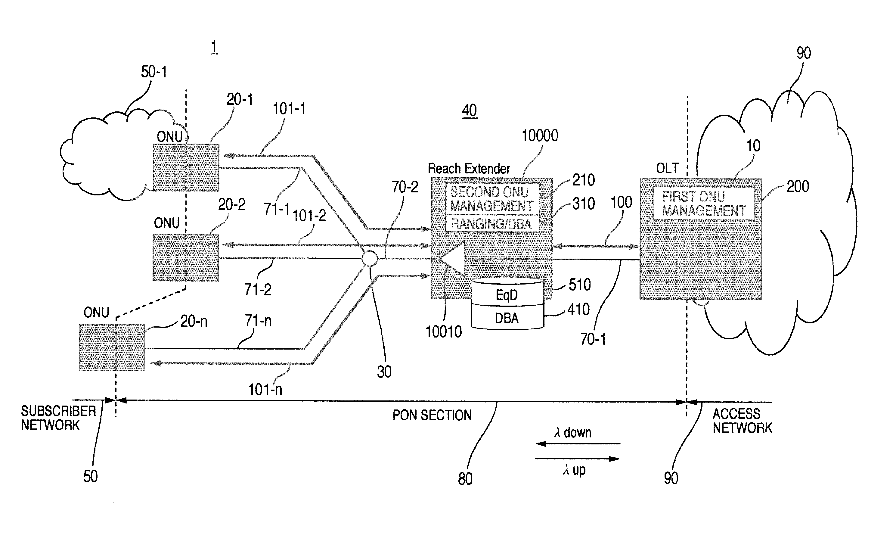
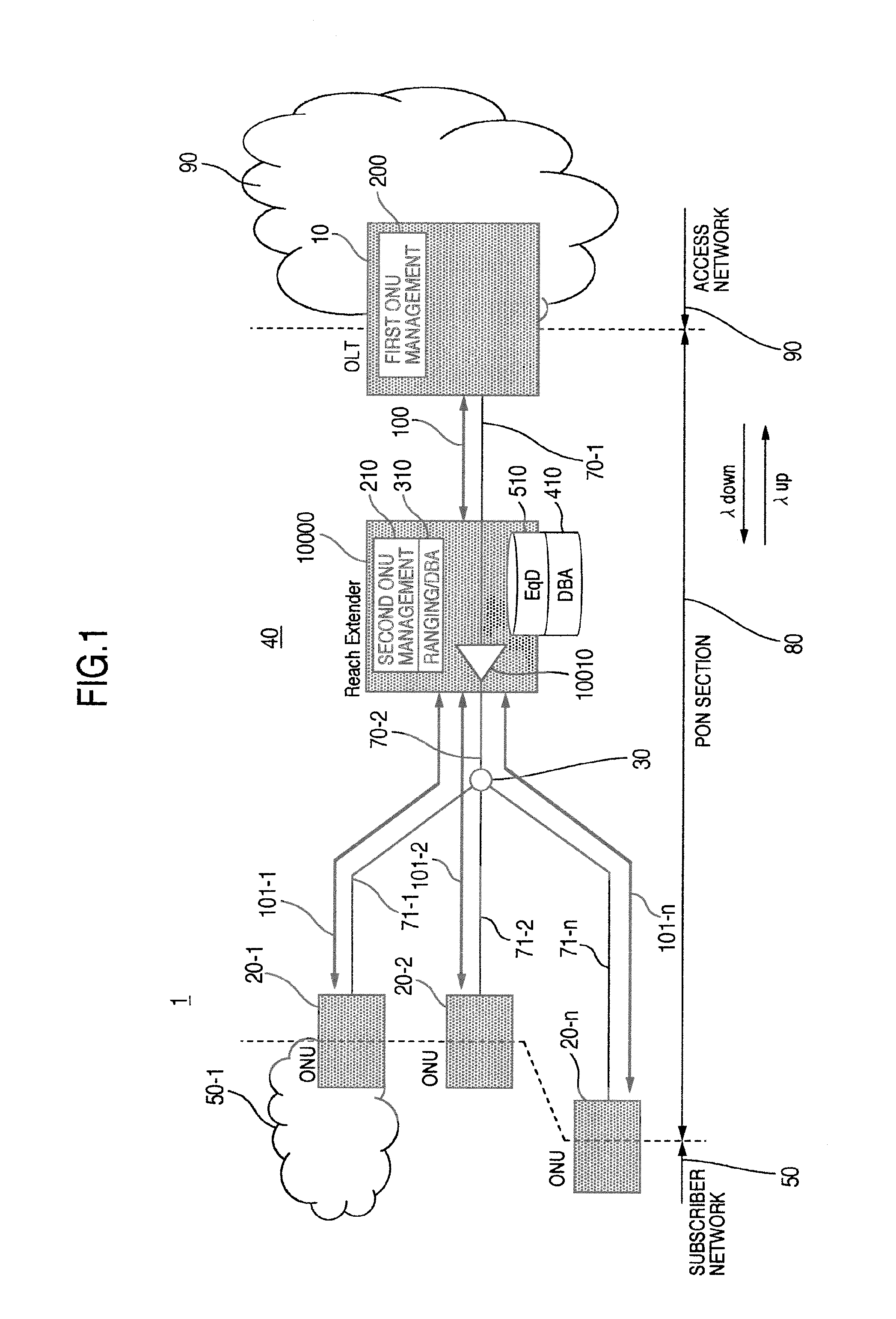
[0033]FIG. 1 is a diagram illustrating an example of the configuration of an optical access network using PON of the present invention wherein RE is inserted into a line concentrator optical fiber of PON.

[0034]PON 40 is constituted of a station side apparatus (OLT) 10, a plurality of subscriber apparatus (ONUs) 20-1 to 20-n, an optical splitter 30, a line concentrator optical fiber 70, a plurality of branch line optical fibers 71-1 to 71-n, and a signal relay apparatus (RE) 10000 inserted between intermediate lines 70-1 and 70-2 of the line concentrator optical Fiber 70. An optical access network 1 of PON connects each of ONUs 20 (20-1 to 20-n) to a subscriber network (or terminals such as PCs and telephones, only a subscriber n...


PUM


Abstract

In the configuration of an optical communication system interconnecting a parent station and a plurality of child stations via an optical fiber network equipped with an optical splitter, RE is provided having a measuring unit for measuring a transmission distance or time to a child station, a determining unit for determining a timing when a child station transmits a signal, in accordance with a transmission bandwidth request from the child station, and a signal processing unit for processing a signal received from a child station and transmitting the processed signal to the parent station. When a burst signal is received from each child station at the determined timing, a portion of the header of the burst signal is deleted, and a dummy signal is inserted into the deleted area and a gap area between received burst signals to convert the burst signals into a series of signals to be sent to the parent station.

Description

BACKGROUND OF THE INVENTION[0001]The present invention relates to the configuration of an optical passive network system in which a plurality of subscriber apparatus share an optical transmission line, and to an operation method for the system, and more particularly to a system configuration and operation method suitable for system extension such as elongation of a transmission distance and an increase in the number of subscriber apparatus.[0002]Because the demand for communications using broadband is so high, access lines of users are changing to large capacity access lines using an optical fiber instead of using techniques of telephone lines such as Digital Subscriber Lines (DSLs). From the viewpoint of line laying and maintenance management cost, widely used as an access network system is a Passive Optical Network (PON) system (hereinafter called simply PON, or an optical passive network system or a passive optical network system where appropriate). PON is a system in which an op...

Claims


Application Information

Patent Timeline
IPC IPC(8): H04B17/02H04L12/44H04B17/40
CPCH04B10/272H04J3/0682H04J3/1694H04J14/0252H04Q2011/0079H04Q2011/009H04J14/0247H04Q11/0067
Inventor MIZUTANI, MASAHIKOYAJIMA, YUSUKETSUCHIYA, AKIHIKO
Owner HITACHI LTD
Learn More