Bearing blocks for drill bits, drill bit assemblies including bearing blocks and related methods

a technology of bearing blocks and drill bits, which is applied in the direction of drilling machines and methods, metal-working drilling tools, constructions, etc., can solve the problems of pdc cutters still suffering from what might simply be termed “overloading, excessive bit aggressiveness, and the like, and achieve the effect of reducing the initial thickness of the bearing block

Inactive Publication Date: 2010-11-04
BAKER HUGHES INC
View PDF100 Cites 94 Cited by
  • Summary
  • Abstract
  • Description
  • Claims
  • Application Information

AI Technical Summary

Benefits of technology

[0013]In some embodiments, the present invention includes a method of drilling a subterranean formation comprising coupling at least one bearing block having at least one rubbing surface and an initial thickness to a drill bit, engaging a formation with at least one cutter of the dri

Problems solved by technology

Even in view of such improvements, however, PDC cutters still suffer from what might simply be termed “overloading” even at low weight-on-bit (WOB) applied to the drill string to which the bit carrying such cutters is mounted, especially if aggressive cutting structures are employed.
The problem of excessive bit aggressiveness is particularly significant in low compressive strength formations where an unduly great depth of cut (DOC) may be achieved at extremely low WOB.
The problem may also be aggravated by drill string bounce or torque and drag, wherein the elasticity of the drill string may cause erratic application of WOB to the drill bit or the drill pipe dragging on the wall of the borehole, with consequent overloading.
Moreover, operating PDC cutters at an excessively high DOC may generate more formation cuttings than can be consistently cleared from the bit face and back up the bore hole via the junk slots on the face of the bit by even the aforementioned improved, state-of-the-art bit hydraulics, leading to the aforementioned bit balling phenomenon.
Another, separate problem involves drilling from a zone or stratum of higher formation compressive strength to a “softer” zone of lower compressive strength.
The abruptly higher torque, in turn, may cause damage to the cutters and/or the bit body itself In directional drilling, such a change causes the tool face or

Method used


Image

  • Bearing blocks for drill bits, drill bit assemblies including bearing blocks and related methods
  • Bearing blocks for drill bits, drill bit assemblies including bearing blocks and related methods
  • Bearing blocks for drill bits, drill bit assemblies including bearing blocks and related methods

Examples


Embodiment Construction

[0035]The illustrations presented herein are not actual views of any particular drilling system, assembly, or device, but are merely idealized representations which are employed to describe embodiments of the present invention.

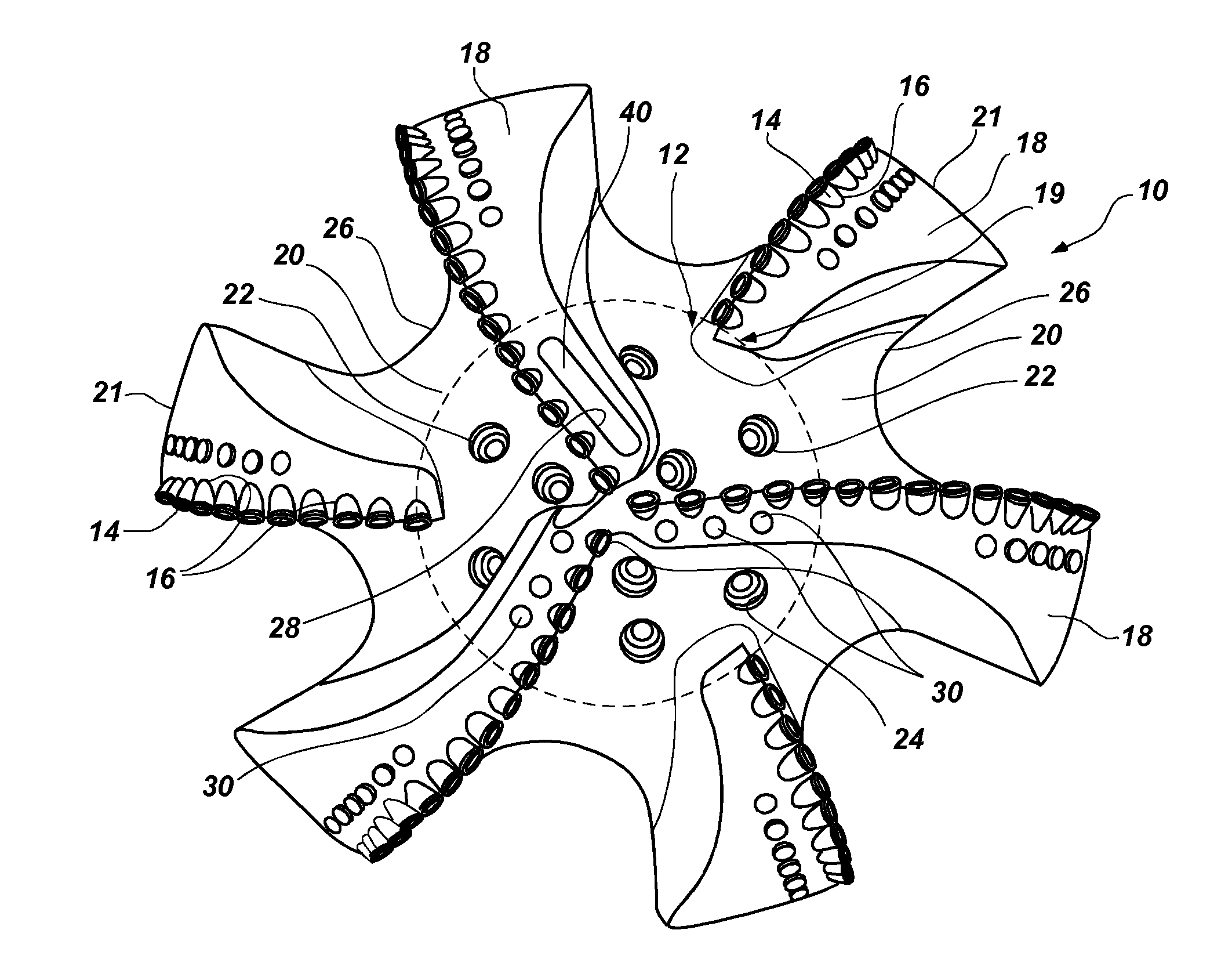
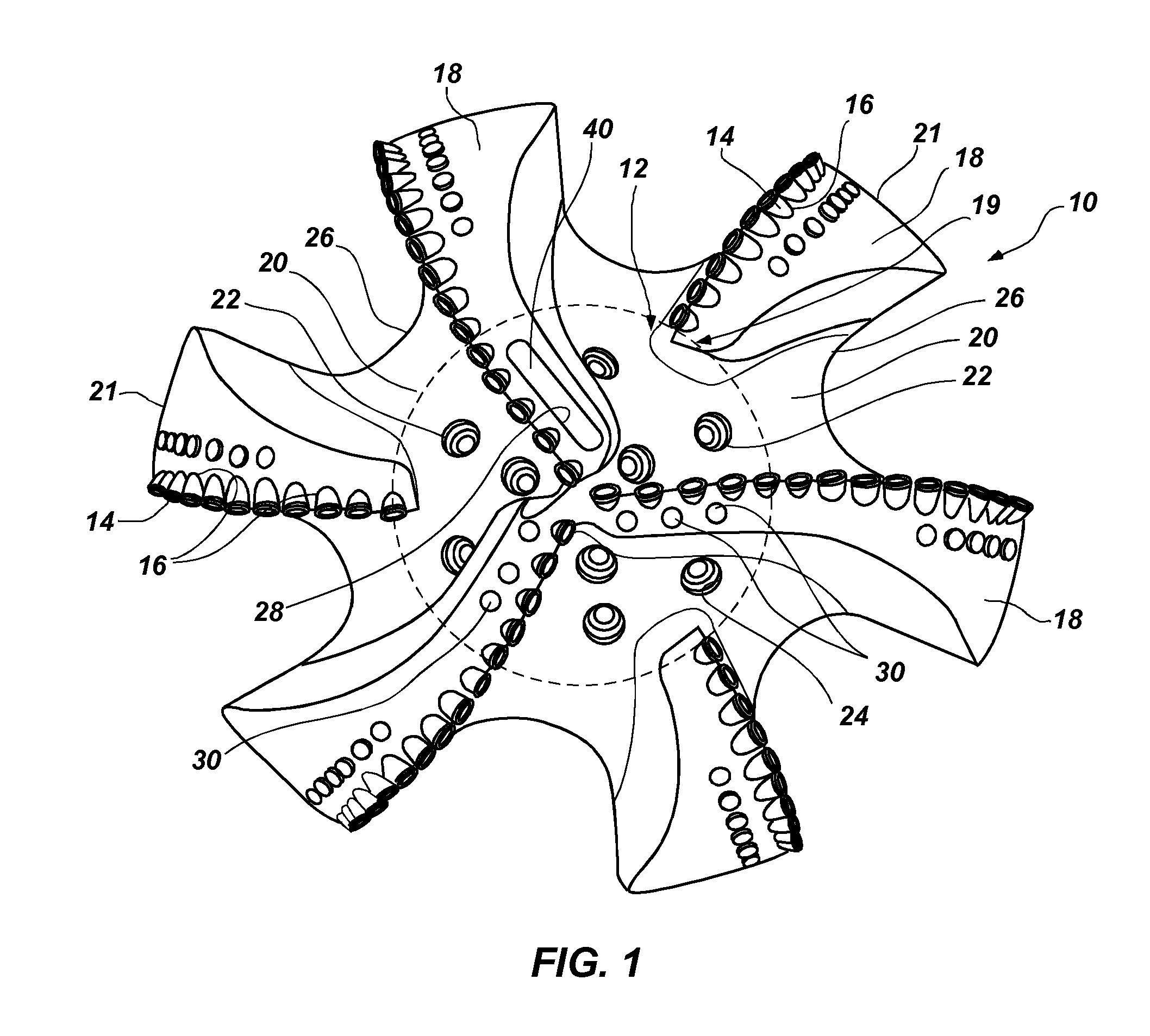
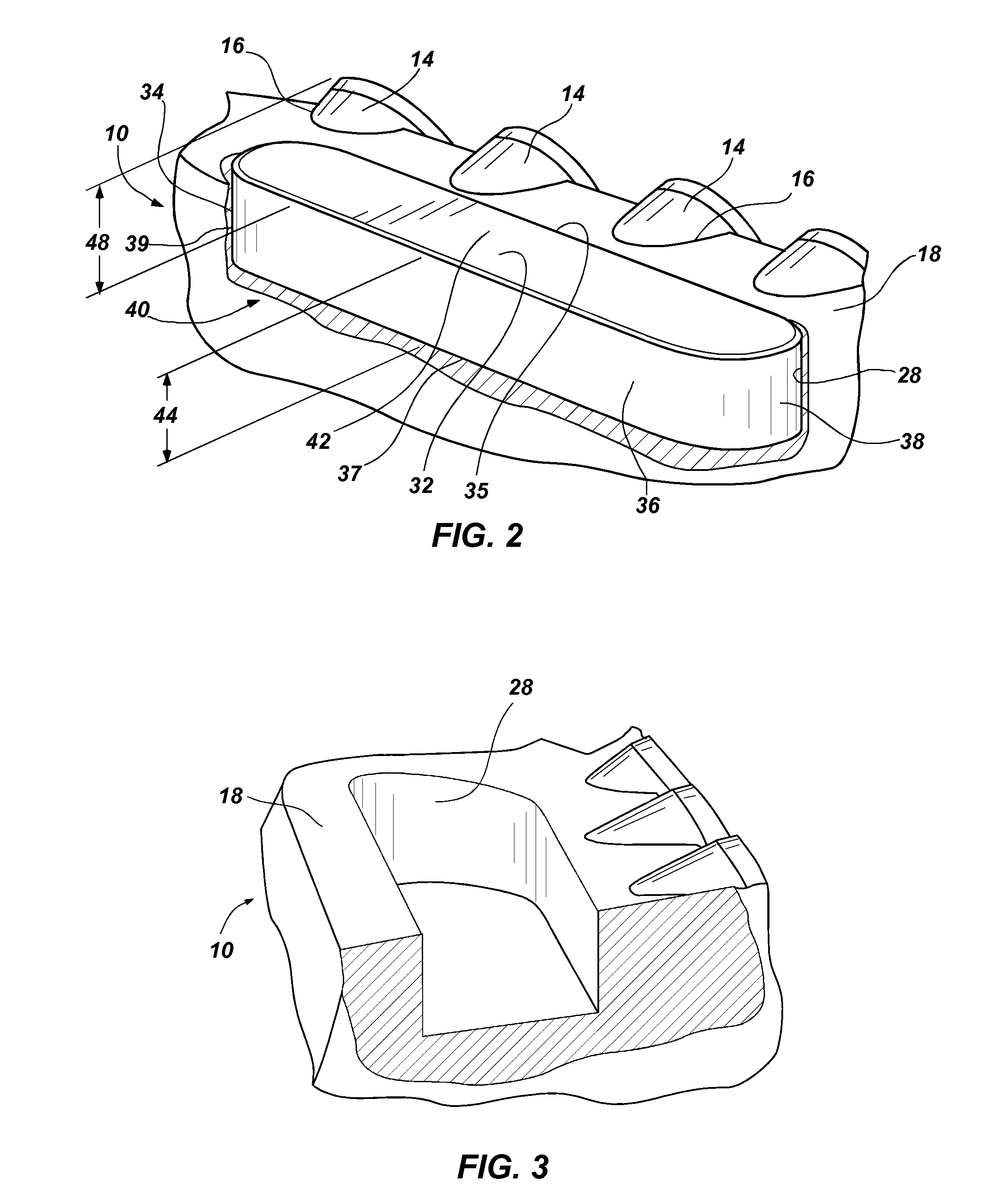
[0036]An embodiment of the current invention is shown in FIGS. 1, 2, 3, and 6. FIG. 1 shows an earth-boring rotary drill bit 10, depicted as a fixed cutter or drag bit employing PDC cutting elements, although of course the invention is not so limited. The bit 10 includes an attached bearing block 40 as viewed by looking upwardly at its face or leading end 12 as if the viewer was positioned at the bottom of a borehole. Bit 10 includes a plurality of PDC cutters 14 bonded by their substrates (diamond tables and substrates not shown separately for clarity), as by brazing, into pockets 16 in blades 18 extending above the face 12 of the bit 10. While the bit 10 depicted in FIG. 1 is a steel body bit, the bit 10 may be fabricated to comprise a particle-matrix compos...


PUM


Abstract

Methods of drilling subterranean formations include coupling at least one bearing block having an initial thickness to a drill bit, engaging a formation with the drill bit within an initial depth of cut range, and reducing the initial thickness of the bearing block by contacting the formation to cause the initial depth of cut range to be at least partially increased. Methods of forming drill bits for drilling subterranean formations include forming at least one rubbing surface of at least one bearing block from at least one material exhibiting a reduced coefficient of friction and coupling the at least one bearing block to the drill bit. Drill bit assemblies include at least one bearing block having a distal portion configured to provide an initial depth of cut range and a base portion configured to provide an increased depth of cut range greater than the initial depth of cut range.

Description

CROSS-REFERENCE TO RELATED APPLICATIONS[0001]This application claims the benefit of U.S. Provisional Patent Application Ser. No. 61 / 174,412, filed Apr. 30, 2009, the disclosure of which is hereby incorporated herein by this reference in its entirety.[0002]The application is also related to, but does not claim priority to, copending U.S. patent application Ser. No. 11 / 818,820, filed Jun. 14, 2007, the disclosure of which is hereby incorporated herein by this reference in its entirety.TECHNICAL FIELD[0003]The present invention, in several embodiments, relates generally to a rotary fixed cutter or “drag” drill bit employing superabrasive cutters for drilling subterranean formations and, more particularly, to use of bearing blocks in association with superabrasive cutters to provide improved accuracy for obtaining one or more target depths of cut for the cutters, a controlled bearing area on the face of the drill bit, or both. Methods of drilling are also encompassed by embodiments of t...

Claims


Application Information

Patent Timeline
IPC IPC(8): E21B10/46E21B7/00E21B10/42E21B10/54E21B10/55B21K5/04
CPCE21B10/55E21B10/43
Inventor SCHWEFE, THORSTENBEUERSHAUSEN, CHAD J.DAMSCHEN, MICHAEL S.
Owner BAKER HUGHES INC
Why Eureka
Try Eureka