Laser scanner with improved decoding

a laser scanner and laser scanner technology, applied in the field of optical scanning systems, can solve the problems of adding cost, complicated improvements, and limited working range of conventional optical scanning systems, and achieve the effects of extending the working range, enhancing the depth of field, and decoding symbol characters faster

Inactive Publication Date: 2010-11-04
HAND HELD PRODS
View PDF0 Cites 21 Cited by
  • Summary
  • Abstract
  • Description
  • Claims
  • Application Information

AI Technical Summary

Benefits of technology

[0005]It is another object of the present invention is to utilize the pre-stored information to provide a scanning apparatus with an enhanced depth of field, thereby allowing a user of the apparatus to decipher symbol characters more quickly.
[0006]It is another object of the present invention is to utilize the pre-stored information to provide a scanning apparatus with an extended working range, thereby allowing a user of the apparatus to decipher symbol characters such as bar codes at a greater range of distances than previous scanning apparatuses.

Problems solved by technology

Conventional optical scanning systems, such as hand-held bar code laser scanners, typically have a limited working range due to the constraints imposed on the optical assembly.
Motorized systems with additional lenses or mirrors have been developed to re-position the laser beam waist relative to the fixed lens assembly, thereby increasing the working range of the scanning apparatus, but such improvements are complicated and add cost.
Decoding images has always proved challenging, in part because decoding systems work best with a sharp representation of the bar code symbol, and a sharp representation is not always possible.
Due to optical, environmental or physical factors, the representation may be out of focus, too close to the reader, or too far away from the reader.
This solution can be cumbersome, frustrating, or may not even be possible.
Various systems have been developed to aide in focusing the laser on the target, such as ranging systems to determine the distance from the reader to the target, but these systems add complexity and cost.

Method used


Image

  • Laser scanner with improved decoding
  • Laser scanner with improved decoding
  • Laser scanner with improved decoding

Examples


Embodiment Construction

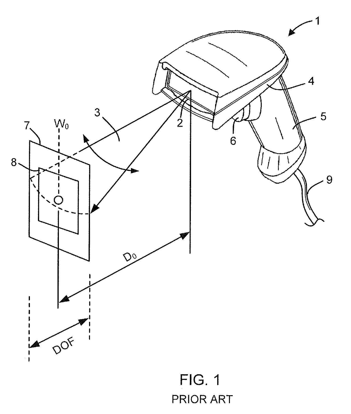
[0018]Referring to FIG. 1, shown is a typical prior art laser bar code reader 1. The reader 1 includes a housing 4 which, in one example, may have a pistol grip handle 5 and a trigger 6. The reader 1 further includes a fixed-lens assembly 2 for focusing a laser beam 3. Pressing the trigger 6 activates the laser beam 3 and allows the lens assembly 2 to focus the beam on a target 7 having optical indicia 8, such as a bar code symbol. The reader 1 may further include a data cable 9 to transfer data from the scanning apparatus to a host computer (not shown).

[0019]The fixed-lens reader 1 operates with the beam 3 focused at a fixed point D0 from the housing. The depth of field (DOF) of the fixed-lens assembly 2 is the linear range about the focused point in which the reader 1 is able to decode the symbol 8. As used herein, depth of field is defined as the distance between the maximum and minimum plane in which a code reader is capable of reading symbols of a specified X dimension (nominal...


PUM


Abstract

A scanning apparatus for decoding an encoded symbol character of a symbology includes a laser source operable to emit a beam along an axis and illuminate a target. The target includes an encoded symbol character. A focusing apparatus in optical communication with the laser source focuses the beam on the target at an object distance, and a detector receives light of varying intensities scattered from the encoded symbol character and converts the light into a first signal. A digitizer converts the first signal to a digital bit stream. The scanning apparatus further includes pre-stored information correlating a non-standard symbol pattern to a valid symbol character according to a standard definition of the symbology. The non-standard symbol pattern comprises a first number of elements that deviates from a second number of elements associated with the valid symbol character. A decoder receives the digital bit stream and utilizes the pre-stored information for decoding the signal.

Description

FIELD OF THE INVENTION[0001]This invention relates generally to the field of optical scanning systems, and more particularly to a system and method for decoding images that increases performance of the system.BACKGROUND OF THE INVENTION[0002]Various optical scanning apparatus have been developed to read and decode optical indicia, such bar as code symbols on a target such as a label. While early bar code scanners were designed to read symbols at a relatively close distance, there exists a need to read symbols at greater and greater distances, for example in warehousing environments. Conventional optical scanning systems, such as hand-held bar code laser scanners, typically have a limited working range due to the constraints imposed on the optical assembly. Motorized systems with additional lenses or mirrors have been developed to re-position the laser beam waist relative to the fixed lens assembly, thereby increasing the working range of the scanning apparatus, but such improvements...

Claims


Application Information

Patent Timeline
Patent Type & Authority Applications(United States)
IPC IPC(8): G06K7/10
CPCG06K7/10801G06K7/10831G06K2207/1016G06K2207/1013G06K2207/1012
Inventor HAVENS, WILLIAM H.MEIER, TIMOTHY P.WANG, YNJIUN P.
Owner HAND HELD PRODS
Why Eureka
Try Eureka