Charged particle optical system comprising an electrostatic deflector

an optical system and charge technology, applied in the direction of instruments, mass spectrometers, beam deviation/focusing by electric/magnetic means, etc., can solve the problems of disadvantages, x and y deflections must be applied sequentially at different angles, and complex construction of deflections, so as to improve the uniformity of scanning, accurately scan a pattern with sufficient speed, and reduce positioning time

Active Publication Date: 2010-11-04
ASML NETHERLANDS BV
View PDF5 Cites 87 Cited by
  • Summary
  • Abstract
  • Description
  • Claims
  • Application Information

AI Technical Summary

Benefits of technology

[0033]Suitably, the modulated beamlet is positioned to a starting position in a positioning period without exposing a target surface, and deflected from the starting position in a writing period. This alternation of positioning and scanning is particularly done as a sawtooth profile. It turns out to improve the uniformity of the scanning.
[0034]Most suitably, the scanning frequency is in a radio frequency (RF) range and each beamlet is deflected in the same orientation as other beamlets both within a scanning period and in subsequent scanning periods; and the positioning period is shorter than the writing period. Herein, it achieved that one may accurately scan a pattern with sufficient speed including high-frequency scanning in one direction combined with a reduction of positioning time by suppressing parasitic capacitance.

Problems solved by technology

The disadvantage of planar deflectors is that x and y deflections must be applied sequentially at different distances (i.e. different z-positions) to a target, for instance a wafer of semiconductor material.
A disadvantage of this deflector type is its complex construction.
This deflection is disadvantageous because a surface area covered by a grid of the beamlets 7 is larger when the beamlets 7 are deflected than when not deflected.
That difference in surface area causes problems for writing a pattern on a target surface that is much larger than the surface area.
However, this type of deflector has the limitation that it provides insufficient uniformity if intended for application as a scanning deflector.
The presence of one of the electrodes on a second substrate leads to the generation of stray fields and hardly controllable effects.
But when applied as scanning deflector, such variation would immediately result in a decrease of the resolution of the provided pattern.
This may result in insufficient resist development and / or wrong beam positioning, and therewith non-adequate (i.e. failed) pattern generation.

Method used


Image

  • Charged particle optical system comprising an electrostatic deflector
  • Charged particle optical system comprising an electrostatic deflector
  • Charged particle optical system comprising an electrostatic deflector

Examples


second embodiment

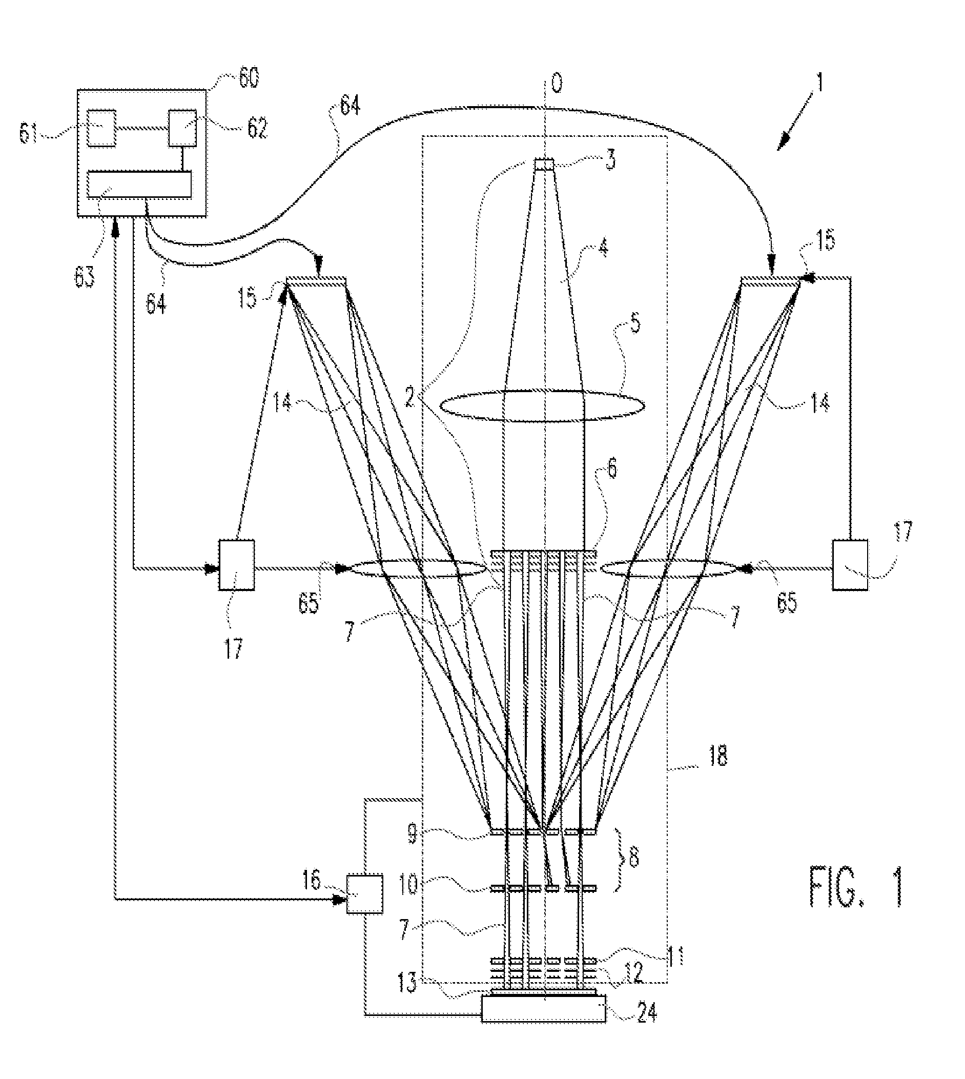
[0083]FIG. 6 shows a top view of a second embodiment according to the invention. This embodiment shows an interdigitated pair of electrodes 21, 22. Edge zones 23 are present located at opposite edges of the deflector 11. The edge zones 23 comprise a set of parallel oriented strips of the first and the second electrode 21, 22. Nonetheless, no passing windows 40 have been designed within the edge zones 23. Suitably, the design of the strips is equal to the design in the main portion of the deflector 9, but that is not necessary. Although shown to be equal, the edge zones 23 might well be implemented in different designs.

[0084]Additionally to the edge zones 23 in a direction parallel to the electric field, it is advantageous to create edge zones 26 in a direction normal to the electric field, i.e. near the distal ends of the freestanding portion of electrodes or strips. Such edge zones 26 support to prevent artifacts in the electric field as a consequence of interactions with the subst...

third embodiment

[0087]FIG. 7 shows a third embodiment according to the invention. In this embodiment, the electrode system comprises several portions 91-94. In this example, the number is four, but that is not necessary or limiting. The number might be larger (for instance 9 or 16), it could be smaller (2). The electrode system may be subdivided into a series of portions adjacent to each other, instead of a plurality of blocks. Each of the portions comprises consecutive strips of electrodes 21, 22 that overlie an aperture 51a-d in the substrate 50. In this embodiment, there are four apertures 51a-d corresponding to the four portions 91-94. However, this is not strictly necessary; an additional layer could act as a carrier for the electrode system of all strips. This additional layer would be provided with apertures 51a-d, while still overlying the aperture 51 in the substrate 50. The apertures 51a-d do not need to have a cubic cross-section, e.g. lateral extension may be larger than width or vice v...


PUM


Abstract

A charged particle optical system comprising a beamlet generator for generating a plurality of beamlets of charged particles and an electrostatic deflector for deflecting the beamlets. The electrostatic deflector comprises first and second electrodes adapted for connection to a voltage for generating an electric field between the electrodes for deflection of the beamlets, the electrodes being at least partially freestanding in an active area of the electrostatic deflector. The electrodes define at least one passing window for passage of at least a portion of the beamlets between the electrodes, the passing window having a length in a first direction and a width in a transverse direction. The system is adapted to arrange the beamlets in at least one row and to direct a single row of the beamlets through the passing window of the electrostatic deflector, the beamlets of the row extending in the first direction. A substantial part of the electrostatic deflector extends beyond the passing window in the first direction.

Description

[0001]This application claims priority to U.S. provisional application No. 61 / 173,638 filed on Apr. 29, 2009, which is hereby incorporated by reference in its entirety.BACKGROUND OF THE INVENTION[0002]1. Field of the Invention[0003]The present invention relates to a charged particle optical system comprising an electrostatic deflector for the deflection of at least one beamlet of charged particles, which deflector comprises a first and a second electrode between which the beamlet passes, which beamlet is deflected upon setting a potential difference between the electrodes.[0004]The invention further relates to the use of such charged particle optical system[0005]2. Description of the Related Art[0006]One such charged particle system is known from U.S. Pat. No. 6,897,458. This system is a maskless lithography system. According to this lithography system, a beam of charged particles, such as electrons, is split in an aperture plate into a plurality of beamlets. The beamlets are subseq...

Claims


Application Information

Patent Timeline
Patent Type & Authority Applications(United States)
IPC IPC(8): H01J37/147H01J3/30H01J37/30
CPCB82Y10/00B82Y40/00H01J37/09H01J37/22H01J37/317H01J2237/2482H01J2237/0437H01J2237/0453H01J2237/1504H01J2237/151H01J37/3174
Inventor BAARS, NORMAN HENDRIKUS RUDOLFTEN BERGE, GERARDUS FERNANDUSSTEENBRINK, STIJN WILLEM HERMAN KAREL
Owner ASML NETHERLANDS BV
Why Eureka
Try Eureka