
Microbial fuel cell

a fuel cell and microorganism technology, applied in the field of microorganism fuel cells, can solve the problem of too large cells to be of practical valu

Inactive Publication Date: 2010-11-04
UNIVERSITY OF CINCINNATI +1
View PDF6 Cites 23 Cited by
  • Summary
  • Abstract
  • Description
  • Claims
  • Application Information

AI Technical Summary

Benefits of technology

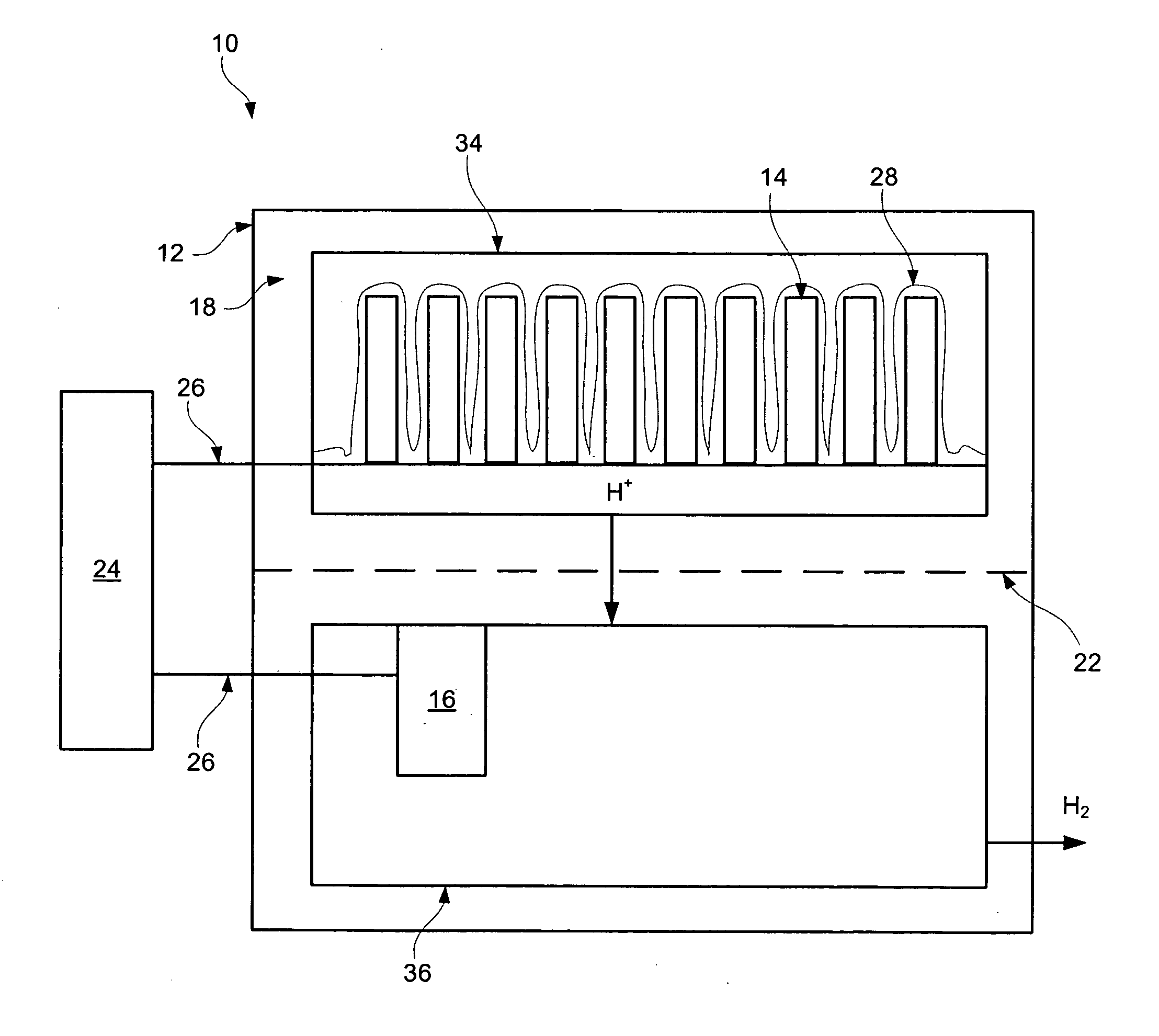
[0011]In an example embodiment, a microbial fuel cell may include cathode(s), anode(s) in electrical communication with the cathode, and a biofilm comprising bacterial cells. The biofilm may be coupled to the anode (which may be electrically conductive material) where the biofilm facilitates transfer of a plurality of electrons from the biofilm to the anode.
[0012]In some examples, the anode may be contained in an anodic chamber and the cathode may be contained in a cathodic chamber. In some examples, a barrier may be located between the anodic chamber and the cathodic chamber. Such barrier may restrict direct transfer of electrons between the anode and cathode.

Problems solved by technology

If the opportunity to modify such characteristics is limited, designers of a fuel cell may have only the anode surface area available as a design variable.
Therefore, an anode with a smaller surface area may suffer from too small power to perform the work needed, or conversely, an anode having a large enough surface area to support the bacteria needed to generate useful amounts power may cause the cell to become too large to be of practical value.

Method used


Image

  • Microbial fuel cell
  • Microbial fuel cell
  • Microbial fuel cell

Examples


example 1

Development of Static Biofilms on Simple Glass Surfaces in Feedstock

[0080]Circular glass coverslips were attached to the bottom of 35×10 mm polystyrene tissue culture dishes with small holes in the base (Falcon). The plates were exposed to UV irradiation overnight. (UV irradiation sterilizes the culture plates).

[0081]Bacterial cells were grown in Luria Bertani media (LB) overnight.

[0082]Aerobic LB, aerobic LBN (LB+1% KNO3), or anaerobic LBN (3 ml) was placed in each tissue culture plate. The media was inoculated with 107 cfu of bacterial cells. The plates were incubated at 37° C. for 24 hours. The media was removed and the plates were washed with saline buffer. LIVE / DEAD BacLight (Molecular Probes, Inc) bacterial viability stain (0.5 ml) was added to each plate. Images were acquired on a Zeiss LSM 510 laser scanning confocal unit attached to an Axiovert microscope with a 63×14 NA oil immersion objective. For two color images, samples were scanned sequentially at 488 nm and 546 nm. S...

example 2

Culture Media

[0083]LB media is 10 g / liter tryptone, 5 g / liter yeast extract, and 5 g / liter NaCl.

[0084]LBN media is 10 g / liter tryptone, 5 g / liter yeast extract, 5 g / liter NaCl and 10 g / liter KNO3.

example 3

Development of Biofilms in Circulated Feedstock

[0085]Bacteria are grown aerobically in LB at 37° C. until the stationary growth phase. Bacteria are diluted 1:50 into 1% trypticase soy broth. Flow cells are inoculated with 0.2 ml diluted bacteria. Flow cells and bacteria are incubated for 1 hour. After an hour, flow is initiated at a rate of 0.17 ml / min. The cells are incubated 3 days at room temperature. The cells are stained with a live / dead viability stain composed of SYTO 9 and propidium iodine (Molecular Probes, Inc.). Biofilm images are obtained using an LSM 510 confocal microscope (Carl Zeiss, Inc.). The excitation and emission wavelengths for green fluorescence are 488 nm and 500 nm, while those for red fluorescence are at 490 nm and 635 nm, respectively. All biofilm experiments are repeated at least 3 times. The live / dead ratios of the biofilms are calculated using the 3D for LSM (V.1.4.2) software (Carl Zeiss). Overall biofilm structure such as thickness, water channel, bac...


PUM


Abstract

Microbial fuel cells may include anode(s), cathode(s) and a biofilm attached to at least the anode. The biofilm may include bacterial cells adapted to facilitate transfer of a plurality of electrons to the anode from a feedstock. In an example embodiment, a microbial fuel surface may include a large surface area to volume ratio in order to increase power (electron) generation and / or transfer.

Description

CROSS-REFERENCE TO RELATED APPLICATIONS[0001]This application claims priority to, and the benefit of, U.S. Provisional Patent Application No. 61 / 154,464, entitled “IMPROVED MICROBIAL FUEL CELL,” filed on Feb. 23, 2009, by Barkeloo et al., the entire disclosure of which is incorporated herein by reference in its entirety.[0002]This application may be related to co-pending U.S. patent application Ser. No. ______, entitled “IMPROVED MICROBIAL FUEL CELL,” filed Feb. 23, 2010, by Barkeloo et al., the entire disclosure of which is incorporated herein by reference in its entirety.FIELD OF THE INVENTION[0003]The present disclosure relates generally to microbial fuel cells having genetically modified organisms. More specifically, it relates to microbial fuel cells having anode(s), cathode(s) and biofilm adapted for improved power (electron) generation and / or improved electron transfer.BACKGROUND OF THE INVENTION[0004]Some bacteria can gain energy by transferring electrons from a low-potentia...

Claims


Application Information

Patent Timeline
IPC IPC(8): H01M8/16
CPCH01M8/16C12N15/78Y02E60/527Y02E60/50
Inventor BARKELOO, JASON E.HASSETT, DANIEL J.IRVIN, RANDALL T.
Owner UNIVERSITY OF CINCINNATI
Learn More