Method And Apparatus For Ultrasonic Bonding

a technology of ultrasonic bonding and ultrasonic welding, which is applied in the direction of gas flame welding apparatus, non-electric welding apparatus, and auxillary devices for welding, etc., can solve the problems of poor bonded connection deformation and current profile, unsuitable for detecting with certainty a bond of inferior quality, and methods that do not achieve the aim

Active Publication Date: 2010-11-04
HESSE
View PDF18 Cites 18 Cited by
  • Summary
  • Abstract
  • Description
  • Claims
  • Application Information

AI Technical Summary

Benefits of technology

[0056]According to the explanations given above, the invention makes it possible to classify errors that are possible during bonding processes, automatically allocate them to error classes and name bonding errors in an automated manner. To this extent, the invention also includes the possibility of generating correction variables in real time in dependence on input textures in the feature extraction and providing feed...

Problems solved by technology

A weakness of this method is that even poor bonded connections may exhibit such deformation and current profiles.
Consequently, the set procedure specified is in any event necessary, but in no way sufficient for determining the quality of a bond, and is therefore unsuitable for detecting with certainty a bond of inferior quality.
These methods do not achieve the aim either, since the measured varia...

Method used


Image

  • Method And Apparatus For Ultrasonic Bonding
  • Method And Apparatus For Ultrasonic Bonding
  • Method And Apparatus For Ultrasonic Bonding

Examples


second embodiment

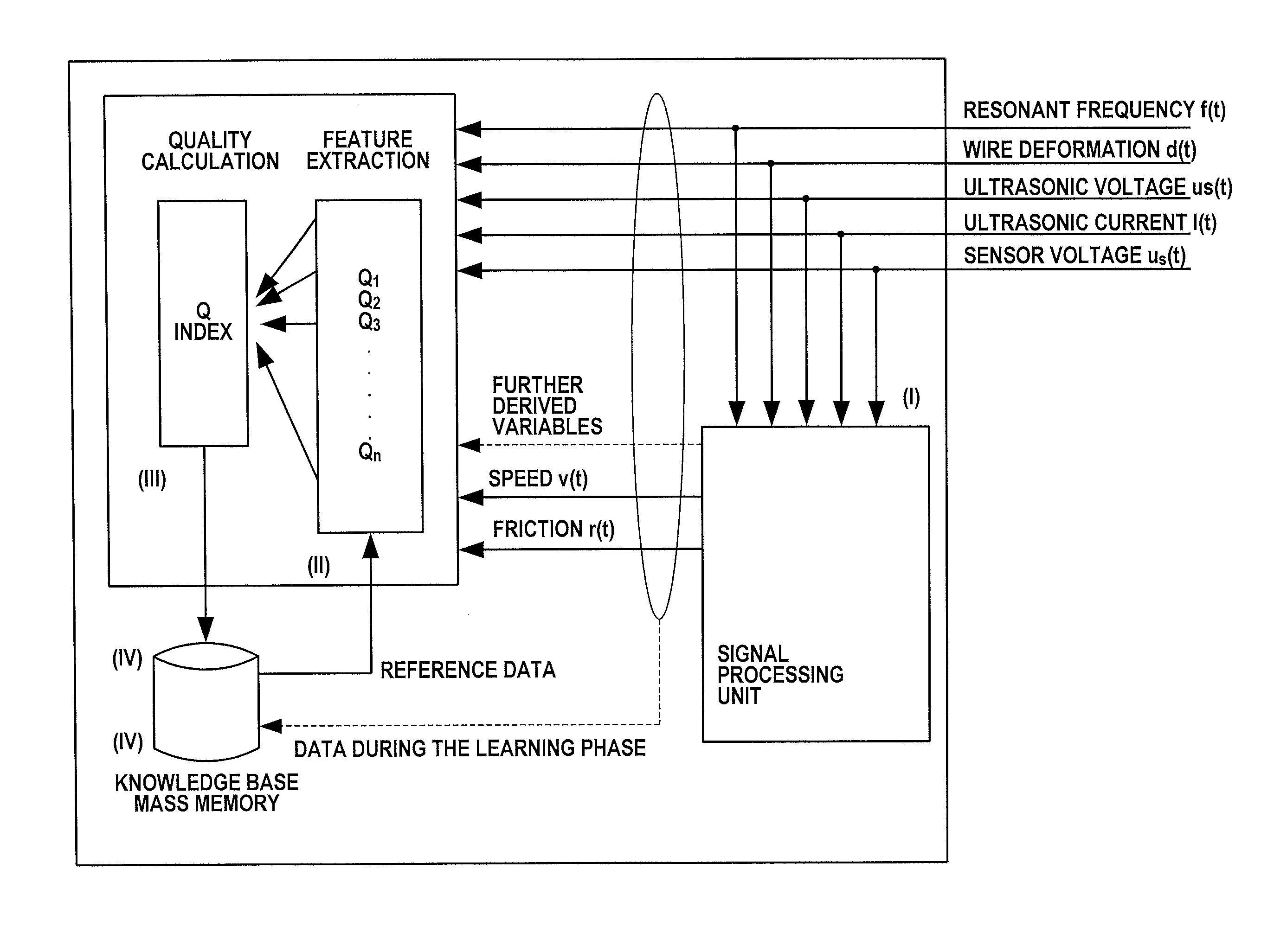
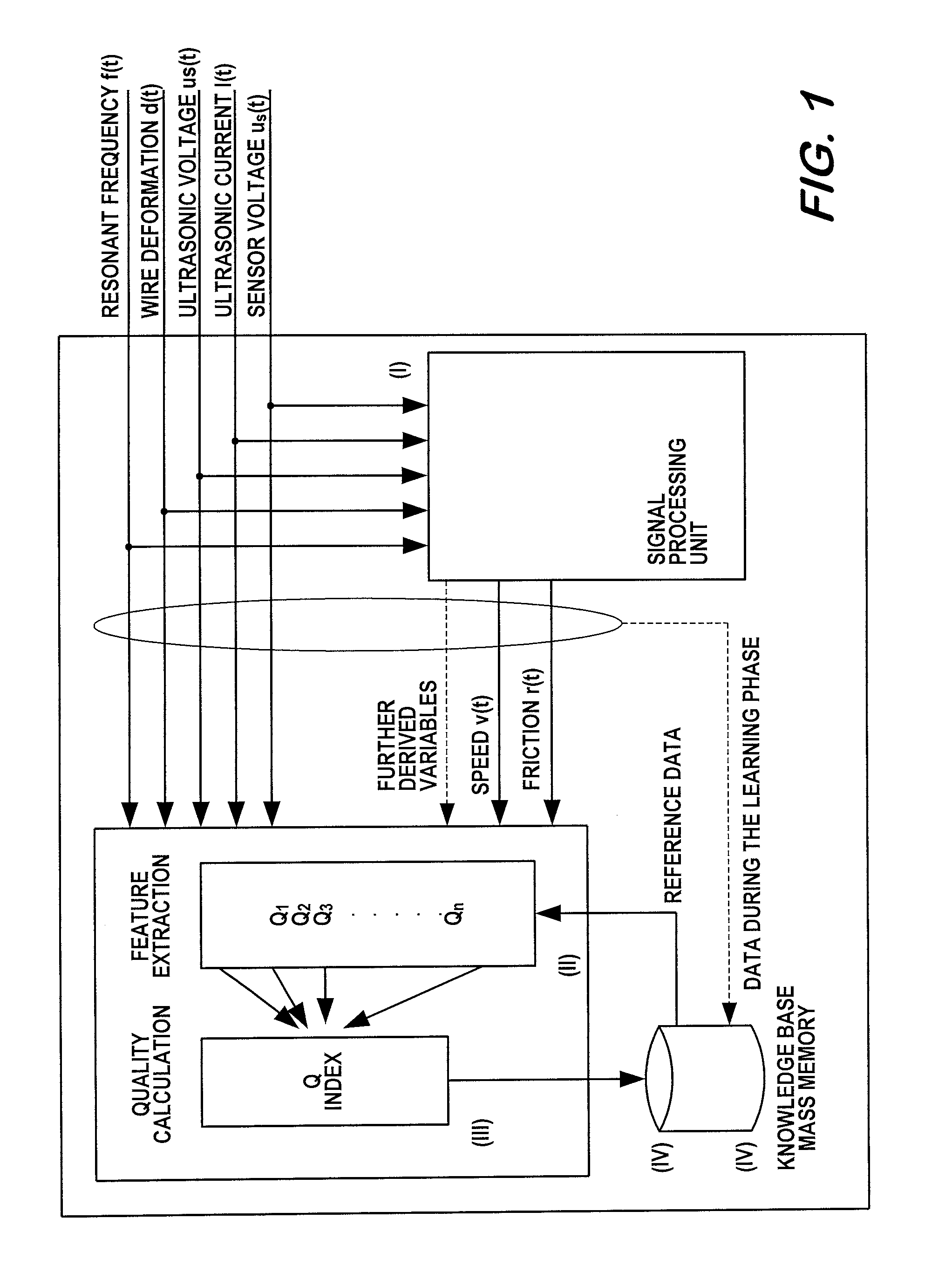
[0074]In continuance or development of the aforementioned possibilities, feature vectors (Q1 . . . Qn) or error vectors may be categorized with regard to their associated error in a further step. FIG. 5 shows the preferred basic construction of a system suitable for this. The calculation of the quality values takes place in principle as described in the A further module, which allocates the result to a result class, and to this extent can specify causes of errors, is provided (cf. FIG. 5, Block 1.3.3).

[0075]The raw data from the signal preprocessing and the ultrasonic generator are not only used for feature extraction (FIG. 5, 1.3.1), but are likewise passed on to a monitoring unit not operating in real time. The monitoring unit likewise receives the result of the quality calculation and of the error classifier (FIGS. 5, 1.3.2 and 1.3.3). The feature extraction, the quality calculation and the error classification each have a further input, via which the results of the monitoring u...

first embodiment

[0080]In Block 1 of FIGS. 7 and 8, essential components of an ultrasonic generator are represented. The comparators 1 and 2 respectively convert the sinusoidal signals for current and voltage into square-wave signals, the zero crossing of which in each case coincides with the zero crossings of the sinusoidal oscillations. Then the phase comparator is used to determine the phase difference between the current and the voltage of the ultrasonic signal. The actual phase value determined in this way is fed to the downstream phase regulator (PID controller) as an input variable. The setpoint phase value for resonance is zero. The output variable of the regulator is the input variable of the DDS (Direct Digital Synthesizer), the variable θcorr is the phase increment on the basis of which the frequency of the output signal of the DDS is set. This signal is then amplified by means of a power amplifier and fed to the ultrasonic transducer. The regulator changes its variable θcorr at the outp...


PUM

PropertyMeasurementUnit
Timeaaaaaaaaaa
Forceaaaaaaaaaa
Densityaaaaaaaaaa

Abstract

A method for quality control during ultrasonic bonding, in which a transducer bonding tool unit and an ultrasonic generator are used and in which, during the bonding, one or more sensors are used to sense measurement signals for one or more parameters, which can vary during the bonding, for assessing the bond quality and/or for influencing the bonding, and which proposes that, during the bonding, at least one speed profile measurement signal representing the time/speed profile of the tip of the ultrasonic tool in the direction of oscillation thereof be sensed. The invention also relates to a bonding apparatus which is suitable for carrying out the method. Furthermore, the invention relates to other quality control methods for ultrasonic bonding and to bonding apparatuses which are suitable for carrying out these methods.

Description

CROSS-REFERENCE TO RELATED APPLICATIONS[0001]The present application is a continuation of pending International patent application PCT / EP2008 / 065101 filed on Nov. 7, 2008, which designates the United States and claims priority from German patent application number 10 2007 054 626.4 filed on Nov. 12, 2007, the content of which is incorporated herein by reference.FIELD OF THE INVENTION[0002]The invention relates to methods for the production and quality control of bonded connections, in particular wire bonded connections, by means of ultrasound, and to components suitable for carrying out these methods as well as to bonding apparatuses equipped with components of this kind, in particular wire bonders. To this extent, the invention also relates in particular to wedge-wedge bonding. The overall aim of the invention is in particular that of improved productivity and improved reliability of the quality control in comparison with conventional techniques.BACKGROUND OF THE INVENTION[0003]Wed...

Claims


Application Information

Patent Timeline
IPC IPC(8): B23K20/10G06F17/00G06F15/18
CPCB23K20/005B23K31/125H01L22/00H01L2924/0002H01L2924/00
Inventor HESSE, HANS-JUERGENBROEKELMANN, MICHAELHAGENKOETTER, SEBASTIAN
Owner HESSE
Why Eureka
Try Eureka