[0011]The present invention has been made in view of the above problems, and an object of the present invention is to provide a carbon fiber heat emitting source formed by providing a bundle of carbon fibers combined with a predetermined amount of glass fibers and by surrounding the bundle with a coating layer, as well as a
heating system using the same. The carbon fiber heat emitting source has high tensile strength while emitting heat at high temperature so that it may not be broken or damaged under tension, may be deformed with ease, and may be applied to boilers and water heaters.
[0012]Another object of the present invention is to provide a nanocarbon heater formed by inserting and sealing carbon fiber yarns into a
quartz pipe along with LPG and
hydrogen and by exposing connection terminals of
nickel wires at both ends of the pipe. The nanocarbon heater may be used as a heat emitting source for a heating lamp,
air heater, heating pipe and boiler to provide excellent
heating efficiency, to maintain a clear indoor environment by avoiding
direct combustion of
oxygen, and to help growth of humans, animals and crops by the emission of
far infrared rays and anions.
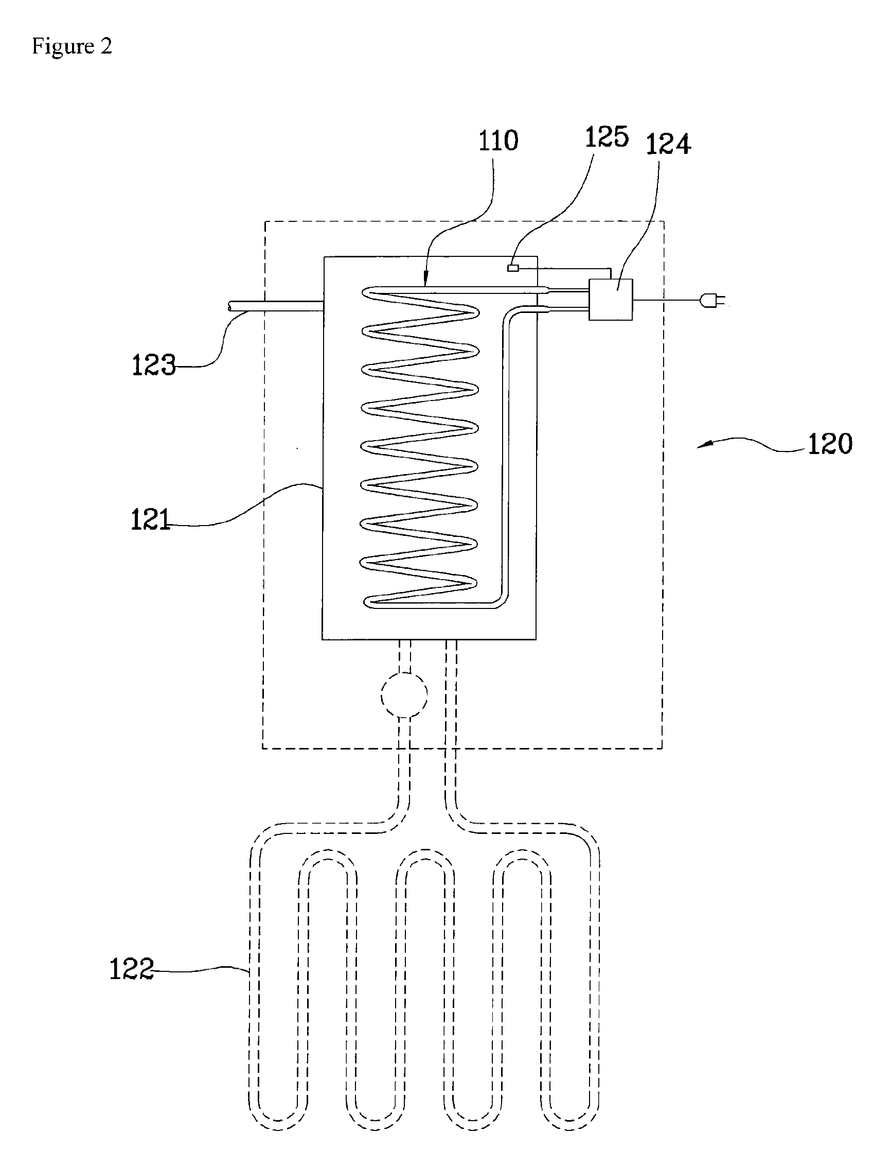
[0013]Still another object of the present invention is to provide a carbon fiber heat emitting source for a
heat exchanger, obtained by providing a bundle of carbon fibers combined with a predetermined amount of glass fibers, coating and binding the outer surface of the bundle with an inorganic
heat resistant ceramic adhesive to form a carbon fiber heat emitting wire, and winding the carbon fiber heat emitting wire onto the exterior of a
water channel pipe, as well as an electric boiler using the same. The carbon fiber heat emitting source directly heats water and efficiently produces hot water via rapid heat exchange. Thus, the electric boiler using the carbon fiber heat emitting source stably and efficiently produces hot water with low
power consumption.
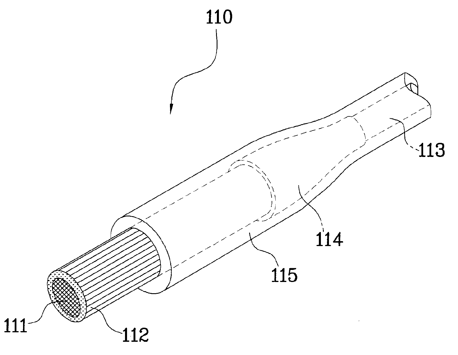
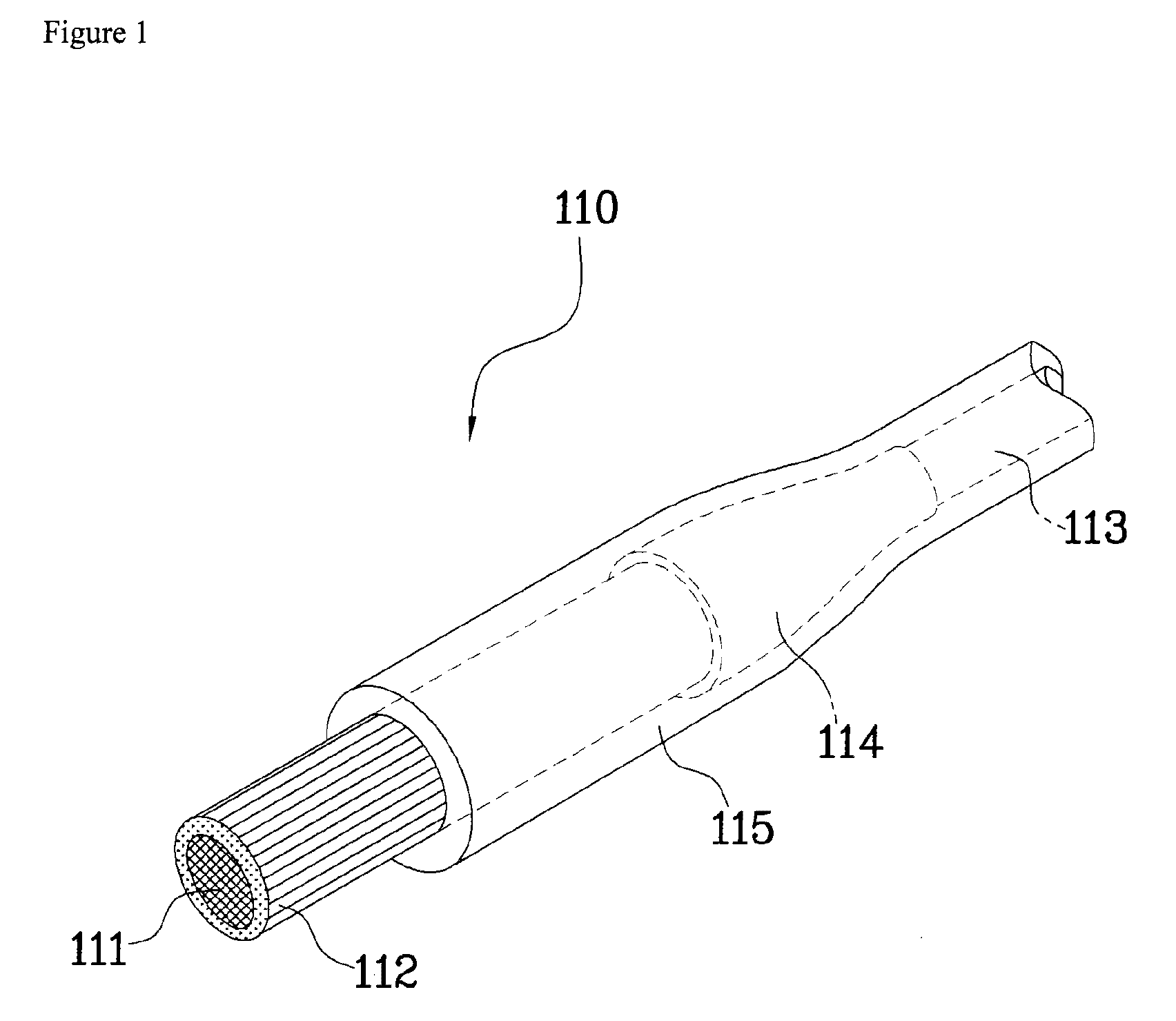
[0031]The carbon fiber heat emitting source according to the present invention includes a bundle of a predetermined amount of glass fibers in combination with carbon fibers emitting heat upon the application of
electricity. Thus, the carbon fiber heat emitting source has high tensile strength derived from the glass fibers and is flexible so that the carbon fiber heat emitting source may be bent in multiple directions. Additionally, the carbon fiber heat emitting source ensures safety so that the carbon fibers are not broken or damaged even under tension. Further, the carbon fiber heat emitting source provides
high energy efficiency because it emits heat at high temperature in a short time with low
power consumption. Therefore, when the carbon fiber heat emitting source is applied as a heater for a boiler or
water heater, the heater has a simple structure, low
power consumption and high efficiency.
[0032]In addition, according to one embodiment of the present invention, carbon fiber yarns formed by twisting multiple strands of the yarns to reinforce tensile force are wound onto an aluminum rod together with
polyester yarns at predetermined intervals, thereby forming a coil-like shape. While the aluminum rod is heated to a temperature of 1500-2000° C. in a heating chamber, the
polyester yarns are mol ten so that the multiple strands of the carbon fiber yarns are integrated therewith and get elasticity. Then,
nickel wires are welded integrally to both ends of the carbon fiber yarns having reinforced tensile force, so that they function as connection terminals for supplying
electric power. After that, the carbon fiber yarns are inserted into a
quartz pipe, LPG and
hydrogen are filled into the quartz pipe under vacuum, and both ends of the quartz pipe are sealed in such a manner that only the both ends of the pipe are exposed, thereby finishing a nanocarbon heater. The nanocarbon heater is installed in front of a reflective plate and electric wires are connected to both connection terminals, thereby providing a heating lamp that allows heating of an indoor space, shows a high calorific value with low power consumption, maintains a clear indoor environment, emits anions and
far infrared rays, and is favorable to the human bodies, animals and crops.
[0033]Further, according to another embodiment of the carbon fiber heat emitting source for a
heat exchanger and an electric boiler using the same, the carbon fiber heat emitting source includes a bundle of carbon fibers emitting heat at high temperature upon the application of
electricity in combination with a predetermined amount of glass fibers, wherein the carbon fibers and glass fibers are bound integrally with each other by an inorganic
heat resistant ceramic adhesive. Since the carbon fiber heat emitting source is wound onto a
water channel pipe, it directly heats the water flowing through the
water channel pipe directly. In this manner, it is possible to perform highly efficient heat exchange, to produce hot water with low power consumption, to realize high tensile strength and flexibility derived from the glass fibers, to prevent oxidation by the inorganic
heat resistant ceramic adhesive coating, to prevent electrical accidents by a heat resistant coating layer, and to realize high safety during use.

