Gasification combustion system

a combustion system and gasification technology, applied in the direction of combustion types, incinerator equipment, lighting and heating equipment, etc., can solve the problems of difficult to establish new landfills, increase the cost of incinerator equipment, and create small amounts of undesirable and potentially harmful byproducts, so as to reduce the emission of harmful products, and the effect of efficient burning of refus

Active Publication Date: 2010-11-18
COVANTA ENERGY CORPORATION
View PDF36 Cites 13 Cited by
  • Summary
  • Abstract
  • Description
  • Claims
  • Application Information

AI Technical Summary

Benefits of technology

[0007]The present invention relates to a gasification combustion system and method which controls the rate of gasification or combustion. By controlling the oxidant supply and temperature of gasification or combustion, the system can more efficiently burn refuse and reduce the emission of harmful products (gases and / or solids) into the atmosphere. Additionally, by controlling the rate and temperature of gasification or combustion, a more durable system can be created which will be more efficient in terms of energy conversion and flue gas processing after MSW thermal treatment.
[0008]Embodiments of the present invention may employ a moving grate that enables the movement of waste through the combustion chamber and thus allows complete combustion of the waste. Additionally, a primary air source and a secondary air source may be utilized. Primary air may be supplied from under the grate and forced through the grate to sequentially dry (evolve water), de-volatilize (evolve volatile hydrocarbons), and burn out (oxidize nonvolatile hydrocarbons) along the waste bed. The quantity of primary air may be adjusted to maximize burn out of the carbonaceous materials in the waste bed, while minimizing the excess air. Secondary air may be supplied through nozzles located above the grate and used to create turbulent mixing that destroys the hydrocarbons that evolved from the waste bed. The total amount of air (primary and secondary) used in the system may vary from approximately 30% to 100% more than the amount of air required to achieve stoichiometric conditions (i.e., the minimum amount of air to theoretically completely combust the fuel).
[0009]The invention may utilize different technologies for reducing the harmful emissions created by conventional MSW combustion systems. For example, combustion controls and post-combustion controls may be used. Combustion controls limit the formation of NOx during the combustion process by reducing the availability of O2 within the flame and by lowering combustion zone temperatures; whereas post-combustion controls involve the removal of the NOx emissions produced during the combustion process (e.g., selective non-catalytic reduction (SNCR) systems and selective catalytic reduction (SCR) systems).
[0012]Certain configurations of the high moisture combustion system may comprise a drier or drying chamber for drying high moisture refuse before it enters a combustion chamber. In such a configuration, air may be delivered to the drier through an under grate gas hopper. The air may be passed through the drier and delivered to the gasifier as secondary air to enhance mixing of oxygen and volatiles from MSW. The secondary air may also be injected into a post combustor to oxidize syngas from the gasifier. The combustion chamber may receive primary air from other gas sources. Through utilizing a drier which recirculates the under grate gas into the gasifier, less air can be infused into the system, reducing the production of fly ash and reducing energy consumption. The system may comprise air nozzles in specific locations and directions to increase air circulation in the post combustor in order to reduce the production of carbon-monoxide. In some embodiments, tertiary air may be injected into the system from a gas source to reduce the production of nitrous oxide. In certain configurations of the system, the recirculated air may be injected in the combustor or post combustor to reduce the amount of unburned carbon content in bottom ash. In some configurations, the system will be able to reduce the moisture content of the refuse to 20% or lower by mass.

Problems solved by technology

Many local authorities, however, have found it difficult to establish new landfills.
In those areas, the solid waste must be transported for disposal, making it more expensive.
One of the problems associated with the conventional combustion of MSW and other solid fuels is that it creates small amounts of undesirable and potentially harmful byproducts, such as NOx, carbon monoxide, and dioxins.
Another problem in the prior art is the unavailability of systems or methods of combusting refuse having high moisture content.
The high moisture content of refuse in countries like China complicates the combustion process because the higher moisture can create unstable combustion because extra heat is needed to dry refuse and leads to lower furnace temperature.
It may be difficult to increase gas flow in conventional systems because the additional gas flow will increase the requirement of fans and decrease boiler efficiency.

Method used


Image

  • Gasification combustion system
  • Gasification combustion system
  • Gasification combustion system

Examples


Embodiment Construction

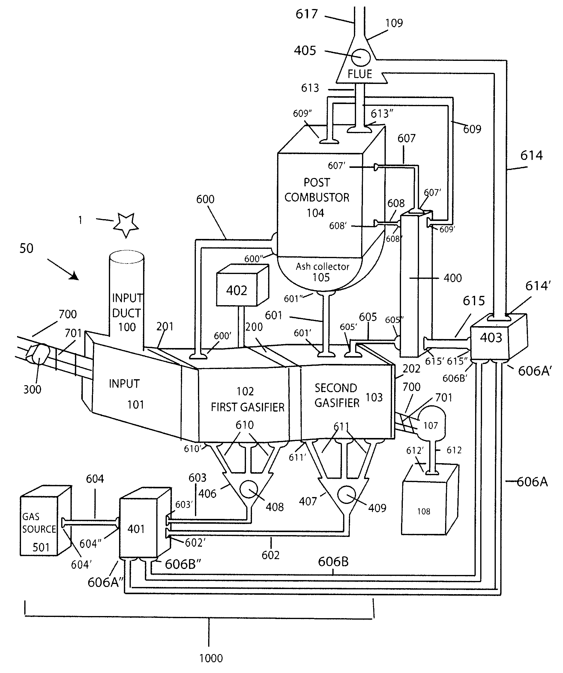
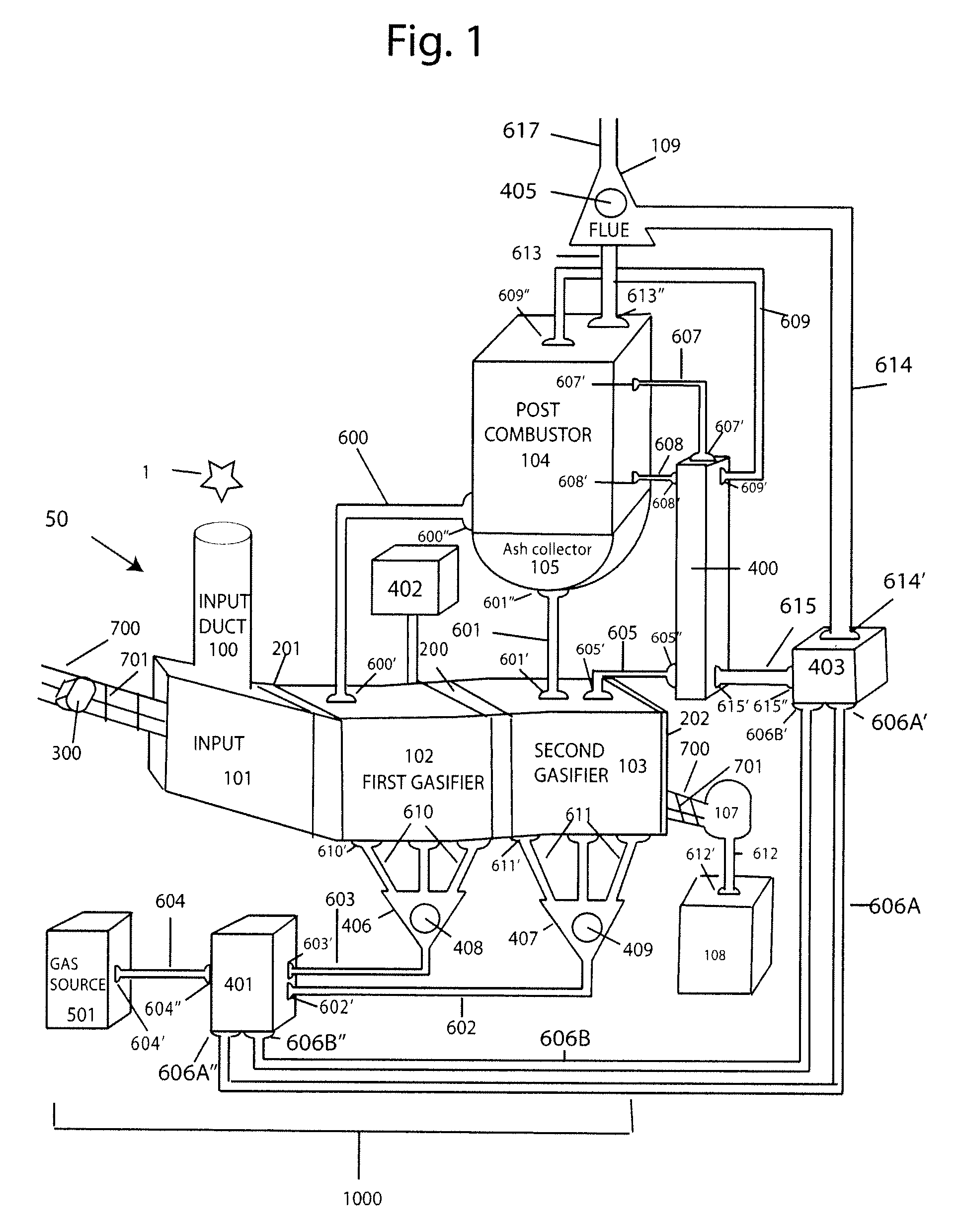
[0024]FIG. 1 illustrates an embodiment of the present invention. The combustion gasification system (broadly denoted as element 50) comprises an input 101 for receiving refuse 1, a first gasifier 102, a second gasifier 103, and a post combustor 104. Refuse 1, trash, or waste may be placed into the input 101 through an input duct 100 containing an outer housing. The input 101 may comprise an opening formed by an outer housing for receiving the refuse. Processing of the refuse 1 typically begins in the first gasifier 102. Processing may include one or more of the following functions: drying, devolatilizing, gasification, or combustion. In some embodiments oil or other flammable substances may be added to the refuse 1 to facilitate combustion.

[0025]Once inside the input 101, the refuse 1 may be advanced through the system 50 by a refuse advancer 700. The refuse advancer 700 may take form of a hydraulic ram 300 and grate 701 as shown in FIG. 1, or a self-advancing advancer may be used. ...


PUM


Abstract

A two stage refuse gasification combustion system for processing refuse is disclosed. The system may contain features such as an advancer, a first and second gasifier, a drier, a gas regulator, and a post combustor. Additionally, methods for regulating gas and advancing refuse through a two stage refuse gasification combustion system are disclosed.

Description

CROSS-REFERENCE[0001]This application is a continuation in part of U.S. application Ser. No. 12 / 467,887 filed May 18, 2009.FIELD OF THE INVENTION[0002]The present invention relates to gasification or combustion systems generally. More specifically, the present invention relates to a method and system for regulating the flow of gas and refuse through a gasifier or combustor system.BACKGROUND[0003]Municipal solid waste (“MSW”) is the gross product collected and processed by municipalities and governments. MSW includes durable and non-durable goods, containers and packaging, food and yard wastes, as well as miscellaneous inorganic wastes from residential, commercial, and industrial sources. Examples include newsprint, appliances, clothing, scrap food, containers and packaging, disposable diapers, plastics of all sort including disposable tableware and foamed packaging materials, rubber and wood products, potting soil, yard trimmings and consumer electronics, as part of an open-ended li...

Claims


Application Information

Patent Timeline
Patent Type & Authority Applications(United States)
IPC IPC(8): F23G5/027F23G5/14
CPCF23C9/00F23G5/027F23G5/04F23G5/16F23G5/50F23G2201/10F23N5/02F23G2202/106F23G2205/00F23G2206/10F23G2207/104F23G2207/20F23N3/00F23G2201/303
Inventor BROGLIO, RONZHANG, HANWEIBARKER, ROBERT LEESGOFF, STEPHEN PAUL
Owner COVANTA ENERGY CORPORATION
Why Eureka
Try Eureka