Piezoelectric type resonance high-voltage light-starting circuit

a high-voltage light-starting circuit and piezoelectric technology, applied in the field of piezoelectric type resonance high-voltage light-starting circuit, can solve the problems of short circuit, high risk, burning out the coil, etc., and achieve the effects of low leakage current, high light-starting efficiency, and small siz

Inactive Publication Date: 2010-11-18
MIDAS WEI TRADING +1
View PDF6 Cites 7 Cited by
  • Summary
  • Abstract
  • Description
  • Claims
  • Application Information

AI Technical Summary

Benefits of technology

[0008]A major objective of the present invention is to provide a piezoelectric type resonance high-voltage light-starting circuit, wherein, the capacitance characteristics of a piezoelectric transformer is utilized as a piezoelectric capacitor in forming a resonance light-starting circuit having its inductor series-connected or parallel-connected with a piezoelectric transformer, thus it is capable of fulfilling the requirements of small leakage current, high light-starting efficiency, and current balance. Furthermore, a booster transformer is connected to an output terminal of the circuit for further amplifying the output voltage, thus facilitating light-starting at high voltage.
[0009]Another objective of the present invention is to provide a piezoelectric type resonance high-voltage light-starting circuit, wherein, a piezoelectric transformer is used to replace the a capacitor or a coil-type booster transformer in a conventional light-starting circuit, hereby achieving smaller size and superior electrical efficacy, and is capable of avoiding the danger of malfunction and overheating due to insufficient voltage endurance. Therefore, its reliability is high, and has a good competitive edge in market competition.
[0010]A further objective of the present invention is to provide a piezoelectric type resonance high-voltage light-starting circuit, wherein, series-connection is adopted in reducing length of wirings utilized, so as to realize the compact size of the final product.
[0011]Therefore, in order to achieve the above-mentioned objective, the present invention provides a piezoelectric type resonance high-voltage light-starting circuit, wherein, a piezoelectric ceramic oscillator plate originally used in high power supersonic wave oscillator is instead utilized in a ballast and an inverter of a resonance light-starting circuit as piezoelectric capacitor. The resonance light-starting circuit having the characteristic that its voltage boost ratio can be varied according to the intrinsic impedance of a load, and that is very suitable for use in driving a light tube. As such, when a light tube is not activated, it is equivalent to be in an open circuit state, at this time, the resonance light-starting circuit can provide fairly high voltage boost ratio in activating and turning on the light tube instantaneously; and when the light tube is activated, the equivalence impedance decreases, so the voltage boost ratio of the circuit also decreases, such that the light tube can operate normally in a stable state.
[0012]In order to meet the requirement of large current and high illuminance, in the present invention, a booster transformer is utilized to raise output voltage to a level required, then the raised voltage is provided to two ends of the respective light tubes, hereby raising the efficiency of power, providing output of high illuminance and shortening the light tube starting time, thus protecting the proper operations of a light tube.
[0013]Meanwhile, the present invention can be applicable in balancing currents in a plurality of light tubes. The intrinsic impedance of an equivalent circuit containing a piezoelectric capacitor is fixed at a constant value through utilizing a fixed frequency, hereby forming a constant current flowing through the light tubes. When the electrical characteristic of a piezoelectric capacitor connected in series with a light tube is close to that of each of the piezoelectric capacitors connected in series with other light tubes, then their intrinsic impedance values are close to each other, so that the current flowing in each of the light tubes is equivalent, thus achieving current balance of light tubes.

Problems solved by technology

However, the disadvantage of this coil type booster transformer is that: its efficiency is not good, and the voltage endurance of coil is not sufficient, thus it is liable be broken down due to sudden jump of power supply to a very high voltage, hereby resulting in a short circuit and burning out the coil, as such, it is highly hazardous.
As shown in FIG. 1, the current difference between light tubes 100 is compensated by a capacitor 110 series connected to a high voltage terminal of a light tube 100, therefore, this tends to cause large leakage current, and its efficiency is not quite satisfactory.
In addition, the voltage endurance of capacitor 110 is not sufficient, a malfunction capacitor 110 tends to explode, and is liable to induce danger of catching fire.
Therefore, due to cost considerations, U-shaped light tubes are utilized in large quantity in the industry.
However, due to the fact that a portion of current and voltage in the bent portions of a U-shaped tube is liable to be lost, as such, sufficient voltage has to be provided in order to achieve the same lighting efficiency as that of a straight and long light tube.

Method used


Image

  • Piezoelectric type resonance high-voltage light-starting circuit
  • Piezoelectric type resonance high-voltage light-starting circuit
  • Piezoelectric type resonance high-voltage light-starting circuit

Examples


Embodiment Construction

[0028]The purpose, construction, features, functions and advantages of the present invention can be appreciated and understood more thoroughly through the following detailed descriptions with reference to the attached drawings.

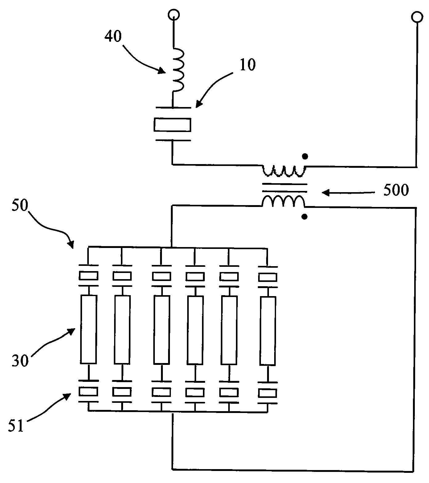
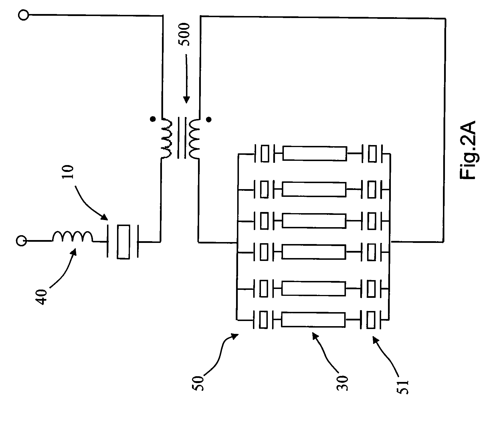
[0029]Refer to FIG. 2A for a circuit diagram of a piezoelectric type resonance high-voltage light-starting circuit according to an embodiment of the present invention. As shown in FIG. 2A, the piezoelectric type resonance high-voltage light-starting circuit mainly includes a plurality sets of cold cathode fluorescence lamps (CCFL) 30, with each set of CCFL connected in series between two auxiliary capacitors 50 and 51, each of the plurality sets of CCFLs 30 is connected to each other in parallel, then the connected set of CCFLs is coupled to a booster transformer 500, and that is series-connected to a resonance inductor 40 and a piezoelectric capacitor 10. In this piezoelectric type resonance high-voltage light-starting circuit, the capacitor characteristic of...


PUM


Abstract

A piezoelectric type resonance high-voltage light-starting circuit, wherein, the intrinsic capacitance characteristic of a piezoelectric transformer is utilized as a piezoelectric capacitor, and said piezoelectric transformer connected to a light tube is connected in series with an independent inductor, thus forming a resonance type series-connected or parallel-connected light-starting circuit, hereby achieving the efficacy of small leakage current, low operating temperature, and high voltage endurance, as such raising the light-starting efficiency. Furthermore, in the application of said circuit mentioned above, output voltage is further amplified through a booster transformer, thus achieving its characteristics of high illuminance. When driving said plurality of light tubes, a fixed frequency is utilized in making an intrinsic impedance of an equivalent circuit containing said piezoelectric capacitor to be fixed at a constant value, thus current flowing in each of said light tubes is equivalent, and achieving balance of currents in said plurality of light tubes.

Description

BACKGROUND OF THE INVENTION[0001]1. Field of the Invention[0002]The present invention relates to a resonance light-starting circuit, and in particular to a piezoelectric type resonance high-voltage light-starting circuit having an independent inductor series-connected or parallel connected with a piezoelectric transformer.[0003]2. The Prior Arts[0004]In general, the lighting principle of Cold Cathode Fluorescence Lamp (CCIF) is the same as that of an ordinary fluorescence lamp, and its lighting principle is that: when a high voltage is input through a terminal of an electrode of a light tube, such that in the light tube, the electrons and molecules are induced to impact on the electrode at high speed, thus generating secondary electron emission. When the electric discharge begins, the electrons will collide with mercury atoms, thus the agitated mercury atoms will radiate 253.7 nm ultra-violet (UV) light, and that will stimulate the fluorescent powder coated on the wall of a light tu...

Claims


Application Information

Patent Timeline
IPC IPC(8): H05B37/00
CPCH05B41/282H05B33/0827H05B45/46Y02B20/00H05B41/24
Inventor WEI, TAO-CHIN
Owner MIDAS WEI TRADING
Why Eureka
Try Eureka