
Near-field light generating device including near-field light generating element with edge part opposed to waveguide

a near-field light and generating element technology, applied in special recording techniques, instruments, record information storage, etc., can solve the problems of increasing the coercivity of the recording medium, reducing the thermal stability of the magnetization of the magnetic fine particles, and difficulty in data recording with existing magnetic heads, so as to increase the use efficiency of light propagation and reduce the spot diameter

Active Publication Date: 2010-11-18
TDK CORPARATION
View PDF4 Cites 37 Cited by
  • Summary
  • Abstract
  • Description
  • Claims
  • Application Information

AI Technical Summary

Benefits of technology

[0016]It is an object of the present invention to provide a near-field light generating device that includes a near-field light generating element having an edge part opposed to a waveguide and that can increase the use efficiency of light propagating through the waveguide and reduce the spot diameter of near-field light, a method of manufacturing the same, and a heat-assisted magnetic recording head, a head gimbal assembly and a magnetic recording device each of which includes the near-field light generating device.
[0025]In the near-field light generating device, the heat-assisted magnetic recording head, the head gimbal assembly or the magnetic recording device according to the present invention, the waveguide has the groove and the clad layer has the opening that is contiguous to the groove. The angle that the first groove sidewall forms with respect to the second direction perpendicular to the top surface of the waveguide is smaller than the angle that the first opening sidewall forms with respect to the second direction. The angle that the second groove sidewall forms with respect to the second direction is smaller than the angle that the second opening sidewall forms with respect to the second direction. The near-field light generating element includes: the first and second side surfaces that are respectively opposed to the first and second opening sidewalls with the buffer layer therebetween, and decrease in distance from each other toward the groove; the edge part that connects the first and second side surfaces to each other and is opposed to the groove with the buffer layer therebetween; and the near-field light generating part that lies at one end of the edge part and generates near-field light. By virtue of such a configuration, the present invention makes it possible to achieve a near-field light generating element that has an edge part having a desired point angle and a small point radius. Consequently, according to the present invention, it is possible to increase the use efficiency of the light propagating through the waveguide and to reduce the spot diameter of the near-field light.
[0026]In the method of manufacturing the near-field light generating device according to the present invention, the buffer layer is formed in the groove of the waveguide and the opening of the clad layer so that the waveguide, the clad layer and the buffer layer constitute a frame for forming the near-field light generating element. The near-field light generating element is then formed in the frame. Such a manufacturing method makes it possible to form a near-field light generating element having a desired point angle and a small point radius. Consequently, according to the present invention, it is possible to increase the use efficiency of the light propagating through the wave guide and to reduce the spot diameter of the near-field light.
[0027]In the method of manufacturing the near-field light generating device according to the present invention, the step of forming the waveguide and the clad layer may include the steps of: forming a preliminary waveguide that is intended to make the waveguide by undergoing formation of the groove therein afterward; forming the clad layer on the preliminary waveguide; and completing the waveguide by forming the groove in the preliminary waveguide by etching the preliminary waveguide with the clad layer used as an etching mask. This allows precise alignment between the groove and the opening, and thus makes it possible to form the near-field light generating element with high precision.

Problems solved by technology

However, making the magnetic fine particles smaller causes the problem that the thermal stability of magnetization of the magnetic fine particles decreases with decreasing volume of the magnetic fine particles.
However, increasing the anisotropic energy of the magnetic fine particles leads to an increase in coercivity of the recording medium, and this makes it difficult to perform data recording with existing magnetic heads.
However, a plasmon antenna that is directly irradiated with light to generate near-field light is known to exhibit very low efficiency of conversion of the applied light into near-field light.
This causes an end of the reproducing head located in the medium facing surface to get farther from the magnetic recording medium, thereby causing the problem that a servo signal cannot be read during recording operations.
In actually fabricating the near-field light generating element, however, there is a problem that the point radius is difficult to reduce particularly when the point angle is somewhat large.

Method used


Image

  • Near-field light generating device including near-field light generating element with edge part opposed to waveguide
  • Near-field light generating device including near-field light generating element with edge part opposed to waveguide
  • Near-field light generating device including near-field light generating element with edge part opposed to waveguide

Examples


Embodiment Construction

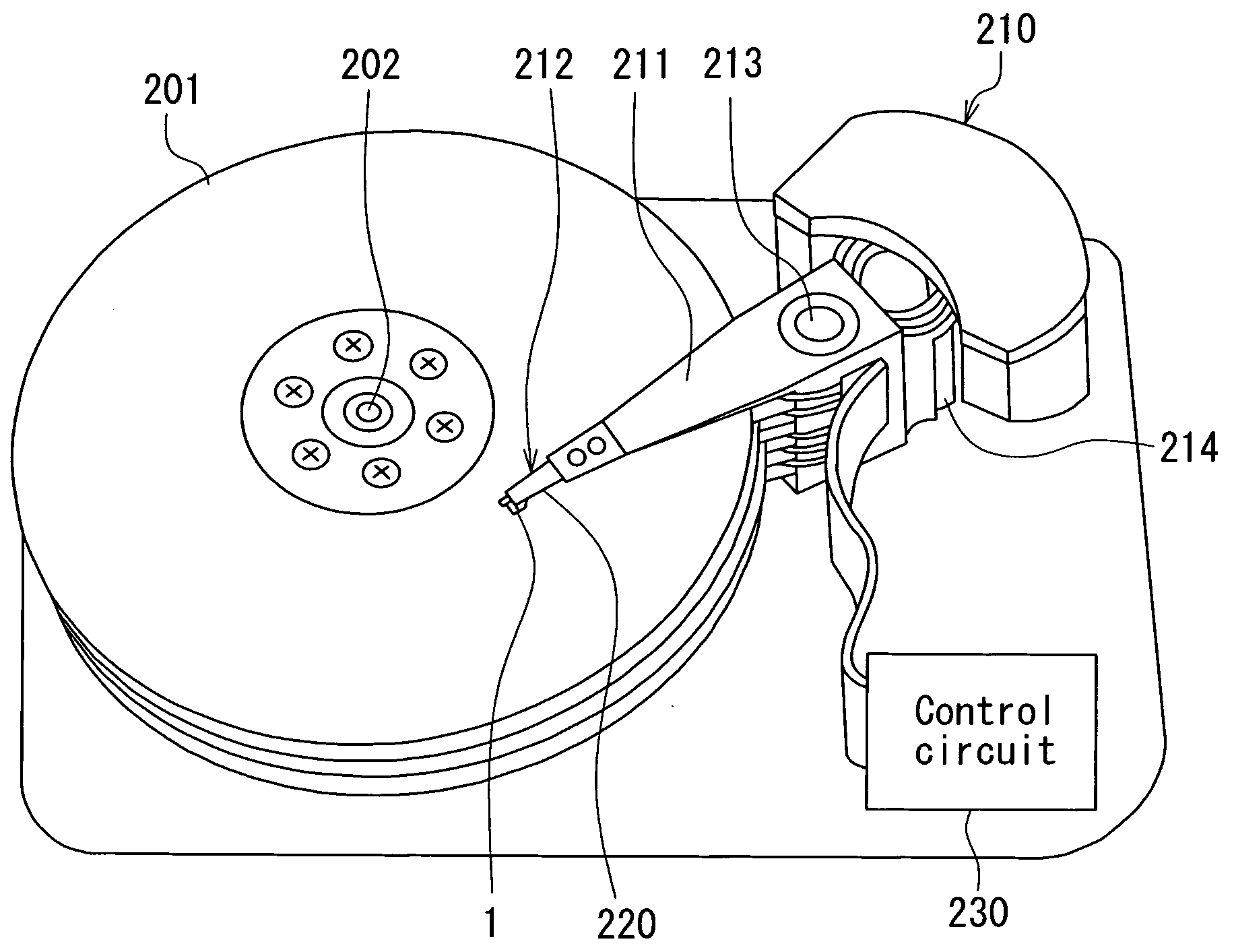
[0055]A preferred embodiment of the present invention will now be described in detail with reference to the drawings. Reference is first made to FIG. 8 to describe a magnetic disk drive as a magnetic recording device according to the embodiment of the invention. As shown in FIG. 8, the magnetic disk drive includes a plurality of magnetic disks 201 as a plurality of magnetic recording media, and a spindle motor 202 for rotating the plurality of magnetic disks 201. The magnetic disks 201 of the present embodiment are for use in perpendicular magnetic recording. Each magnetic disk 201 has such a structure that a soft magnetic backing layer, a middle layer and a magnetic recording layer (perpendicular magnetization layer) are stacked in this order on a disk substrate.

[0056]The magnetic disk drive further includes an assembly carriage device 210 having a plurality of driving arms 211, and a plurality of head gimbal assemblies 212 attached to respective distal ends of the driving arms 211...


PUM

PropertyMeasurementUnit
Fractionaaaaaaaaaa
Fractionaaaaaaaaaa
Fractionaaaaaaaaaa

Abstract

A near-field light generating device includes: a waveguide having a groove that opens in the top surface; a clad layer disposed on the top surface of the waveguide and having an opening that is contiguous to the groove; a near-field light generating element accommodated in the opening; and a buffer layer interposed between the near-field light generating element and each of the waveguide and the clad layer in the groove and the opening. The near-field light generating element includes: first and second side surfaces that decrease in distance from each other toward the groove; an edge part that connects the first and second side surfaces to each other and is opposed to the groove with the buffer layer therebetween; and a near-field light generating part that lies at one end of the edge part and generates near-field light.

Description

BACKGROUND OF THE INVENTION[0001]1. Field of the Invention[0002]The present invention relates to a near-field light generating device for use in heat-assisted magnetic recording where a magnetic recording medium is irradiated with near-field light to lower the coercivity of the magnetic recording medium for data recording, and a method of manufacturing the same, and to a heat-assisted magnetic recording head, a head gimbal assembly, and a magnetic recording device each of which includes the near-field light generating device.[0003]2. Description of the Related Art[0004]Recently, magnetic recording devices such as a magnetic disk drive have been improved in recording density, and thin-film magnetic heads and magnetic recording media of improved performance have been demanded accordingly. Among the thin-film magnetic heads, a composite thin-film magnetic head has been used widely. The composite thin-film magnetic head has such a structure that a reproducing head including a magnetores...

Claims


Application Information

Patent Timeline
IPC IPC(8): G11B11/00G11B5/02G11B5/48C23C16/06
CPCG11B5/314G11B5/4826G11B2005/0021G11B2005/001G11B5/6005
Inventor ISOGAI, MAKOTOAOKI, SUSUMUMIYAUCHI, DAISUKEKOMURA, EIJITAKAYAMA, SEIICHI
Owner TDK CORPARATION
Learn More