
Encoder, decoder, encoding method, and decoding method

a technology of encoding and decoding schemes, applied in the direction of coding, code conversion, cyclic codes, etc., can solve the problems of slow response, significant decrease in object transmission speed, complex apparatuses, etc., and achieve optimal redundancy of error-correcting codes and optimal volume of transmitted information

Inactive Publication Date: 2010-11-18
SAMSUNG ELECTRONICS CO LTD
View PDF18 Cites 17 Cited by
  • Summary
  • Abstract
  • Description
  • Claims
  • Application Information

AI Technical Summary

Benefits of technology

[0012]An object of the present invention is the creation of an encoder, transmission apparatus, and an information object transmission system, enabling the considerable increase of transmission speed of information objects compared to existing devices and systems, using an optimal volume of the transmitted information and optimal redundancy of the error-correcting code in the chosen communication channel. Creation of such apparatuses and the system will enable transmission of the information objects of any size, which will increase their scope of application considerably.
[0014]Control data, including the object size and the current sample number is encoded with high redundancy. Then the samples and the control packet of the optimal volume are combined into the data packet for transmitting, which is converted to the signal for transmission through the communication channel. The information object is transmitted by continuous transmission of pseudorandom data packets through the communication channel, which enables error-free reception of large information objects at a high speed during iterative decoding.
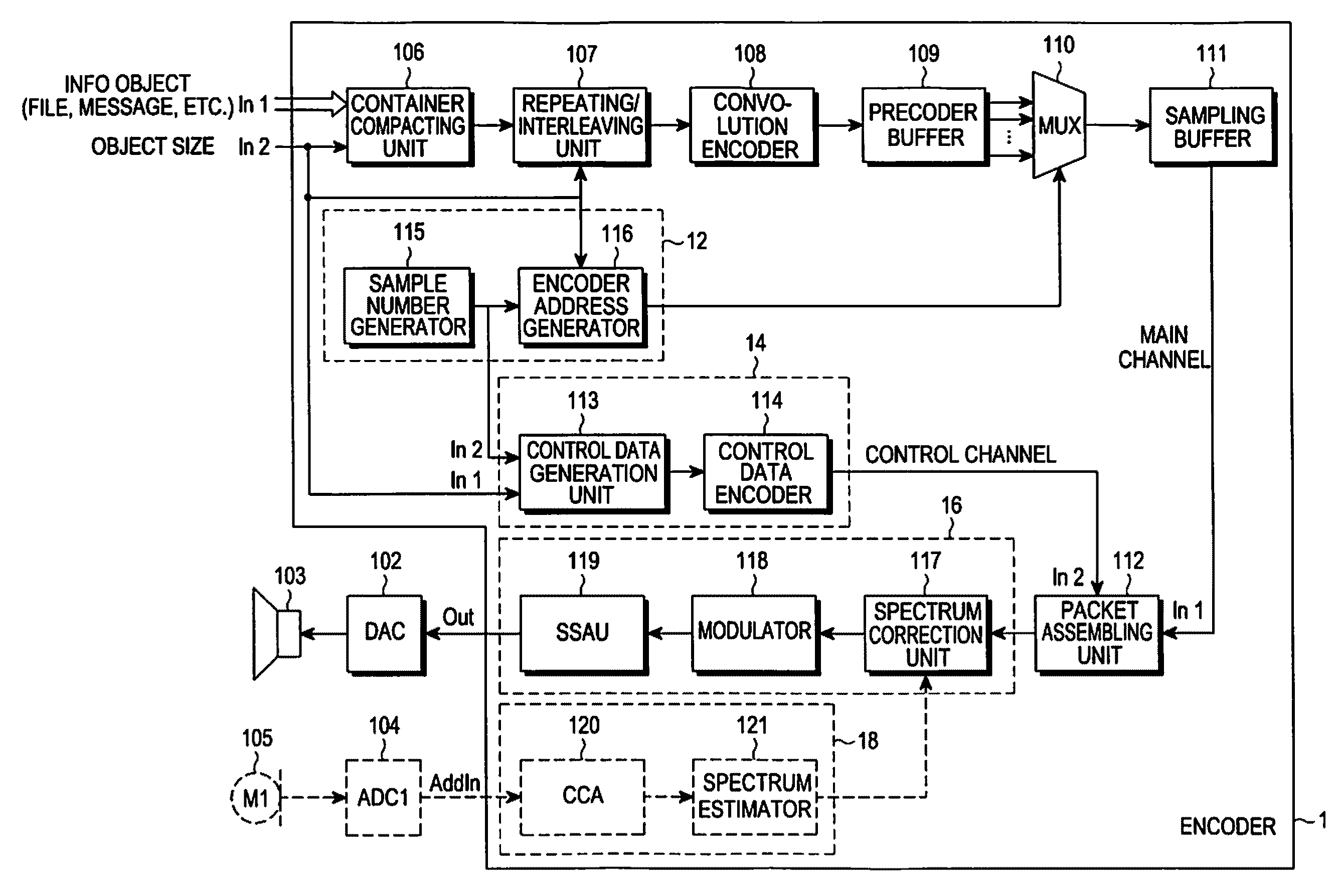
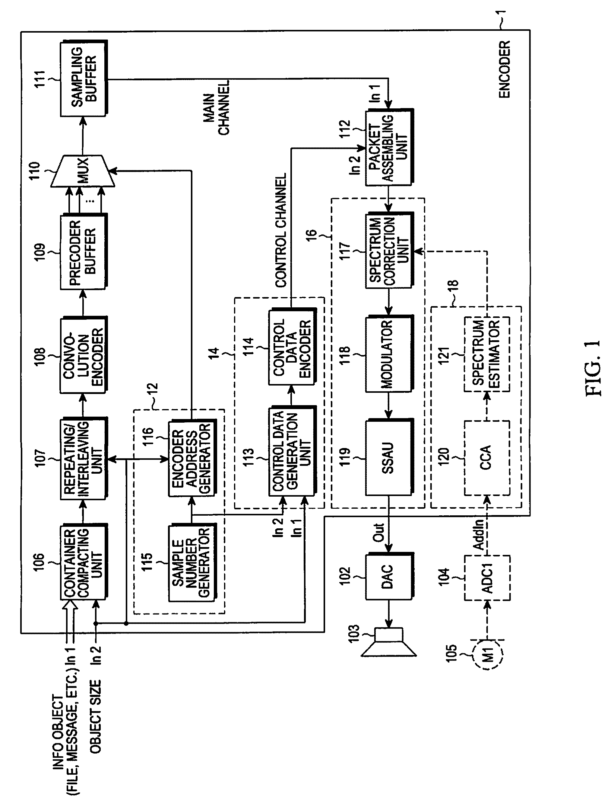
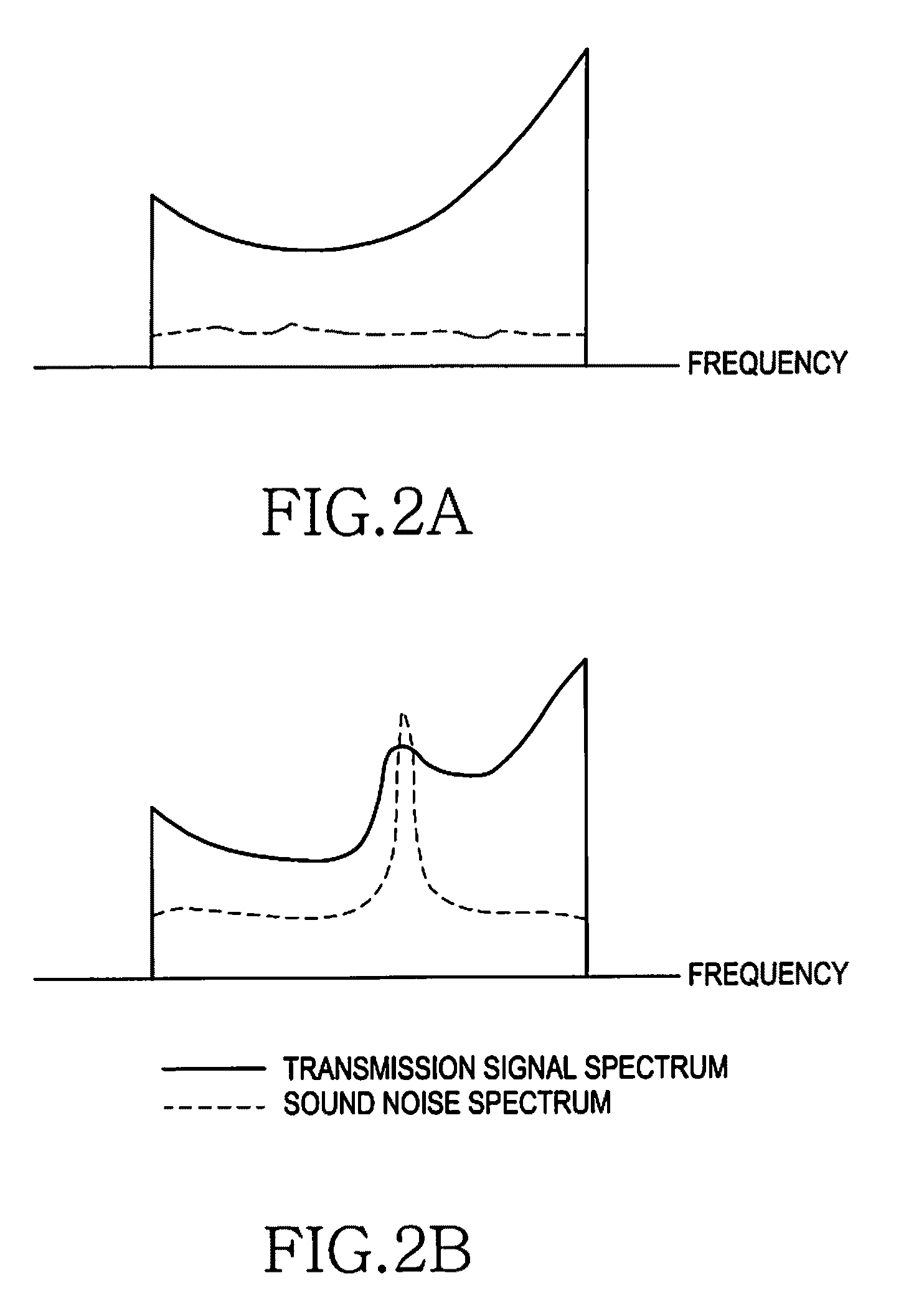
[0022]The additional input of the encoder is coupled to the spectrum corrector through the successively connected communication channel analyzer and spectrum estimator. It enables the provision of a dynamic response to the changing interference-environment in the communication channel.
[0025]The Microphone M1 of the transmission apparatus is connected to the additional input of the encoder, being the additional input of the transmission apparatus and connected to the spectrum corrector through the successively connected communication channel analyzer and spectrum estimator, through the analog-to-digital converter of the transmission apparatus. Thus enabling the provision of a dynamic response to the changing interference (particularly acoustic) environment in the communication channel, at the same time using peculiarities of the aural perception of acoustic noises by the human.
[0036]The present invention creates the encoder, transmission apparatus, and the information object transmission system, enabling the considerable increase in transmission speed of information objects compared to existing devices and systems, using an optimal volume of the transmitted information and optimal redundancy of the error-correcting code in the chosen communication channel.

Problems solved by technology

High noise immunity of data transfer is usually achieved by means of encoding with a high level of redundancy, enabling transmission of the objects with an increased probability of error-free reception in the communication channel with considerable interference, but causing a significant decrease in the object transmission speed on the other hand.
A drawback of such systems is the complexity of apparatuses in receiving and transmitting section, since a feedback mechanism is obligatory between the apparatuses in the receiving and transmitting sections (each of them must contain transceiver); slow response to the changing noise situation and, as a consequence, low rate of information objects transmission.
The drawback of the system is its inefficiency.
Thus, during objects transmission, especially of a large amount of data, the possibility of erroneous reception increases drastically, and the transmission speed decreases and can not be optimal for the arbitrary signal to noise ratio in the communication channel.
Therefore, an information object transmission either with high noise immunity (a lot of redundant (checking) data during object encoding) is necessary so that the error-free reception can be provided by means of one-two repetitions, which affects the speed, or increased transmission speed, in which case, noise increase in the communication channel adversely affects the noise immunity and the object may not be received at all.

Method used


Image

  • Encoder, decoder, encoding method, and decoding method
  • Encoder, decoder, encoding method, and decoding method
  • Encoder, decoder, encoding method, and decoding method

Examples


Embodiment Construction

[0042]Embodiments of the present invention are described in detail with reference to the accompanying drawings. The same or similar components may be designated by the same or similar reference numerals although they are illustrated in different drawings. Detailed descriptions of constructions or processes known in the art may be omitted to avoid obscuring the subject matter of the present invention.

[0043]The transmission apparatus of the system, presented on FIG. 1, includes an encoder 1, the first input (In1) and the second input (In2) of which are informational. Digital to analogue converter (DAC 102) and loudspeaker 103 are successively connected to the output of the encoder. To the additional input (ad. Input) of the encoder, intended for communication channel diagnostics, through analog-to-digital converter ADC104 of the transmission apparatus encoder, the microphone (M1) of the transmission apparatus 105 is connected.

[0044]The encoder 1 includes a precoder 10 for encoding an ...


PUM


Abstract

An encoder includes a precoder for encoding an input information object according to a preset encoding scheme and storing the encoded information object in a precoder buffer, a sample number / address generation unit for generating a sample number of each sample and an address, which corresponds to each bit of each sample and the address of the precoder buffer, a multiplexer for selecting a bit of the precoder buffer corresponding to the address generated by the sample number / address generation module, a sampling buffer for storing a bit of each sample output from the multiplexer, a control packet generation module for generating a control packet including information on the sample number generated by the sample number / address generation module, a packet assembling unit for assembling the sample stored in the sampling buffer with the control packet generated by the control data generation module, and a modulation module for modulating the packet output from the packet assembling unit into a sound signal according to a preset scheme.

Description

PRIORITY[0001]This application claims priority to an application filed with the Russian Intellectual Property Office on May 18, 2009 and assigned Serial No. RU2009119776 and the Korean Intellectual Property Office on Apr. 9, 2010 and assigned Serial No. 10-2010-0032589, the contents of which are incorporated herein by reference.BACKGROUND OF THE INVENTION[0002]1. Field of the Invention[0003]The present invention relates generally to encoding and decoding schemes and data transmission and reception devices for wireless communication systems, and more particularly to facilitating the systems of short-range communication between stationary or mobile devices and mobile (including portable) devices, using an acoustic communication channel for data transfer over short distances.[0004]2. Description of the Related Art[0005]Encoding and data transfer apparatuses, used for different types of communication channels are widely known, and include a disassembler for disassembling an information ...

Claims


Application Information

Patent Timeline
Patent Type & Authority Applications(United States)
IPC IPC(8): H04J3/24H04L47/43
CPCH03M13/09H03M13/096H03M13/15H03M13/27H03M13/2936H04J3/24H03M13/6356H04L1/0041H04L1/007H04J3/04H03M13/2957
Inventor JUNG, HEE-WONPARK, SEUNG-GUNLEE, GI-SANGKOH, JUN-HOLEE, SANG-MOOKZHIDKOV, SERGEY
Owner SAMSUNG ELECTRONICS CO LTD
Learn More