Device for implanting in a human or animal vertebral column

a vertebral column and implant technology, applied in the field of human or animal spine implanting devices, can solve the problems of pain or other disabilities, high manufacturing cost, restricted free movement of patients provided with such implants, etc., and achieve the effect of low manufacturing cost and complete freedom of movement of the spin

Inactive Publication Date: 2010-11-18
METZ STAVENHAGEN PETER
View PDF5 Cites 21 Cited by
  • Summary
  • Abstract
  • Description
  • Claims
  • Application Information

AI Technical Summary

Benefits of technology

[0009]In view thereof, it is the object of the present invention to provide a device for implantation in a human or animal spine that ensures at low manufacturing cost complete freedom of movement of the spine.
[0011]A device for implantation in a human or animal spine configured according to this technical teaching has the advantage that the elastic element, which is configured in the form of an undulated bellows, is pivotal in any direction while exhibiting sufficient stiffness to obviate the need for further connection between the base carrier and the top carrier. The undulated bellows further has the advantage that bending may occur in the desired direction without high forces acting thereby onto the base carrier and / or the top carrier. AS a result, the load on the screws fixing the base carrier and / or the top carrier is kept low.
[0012]In a preferred embodiment, undercuts, more specifically in the form of a dovetail joint, are provided in the base carrier and / or in the top carrier on the side turned toward the undulated bellows for interlockingly receiving the parts of the undulated bellows. It is thereby readily possible to for example first introduce the undulated bellows into the base carrier in such a manner that the last undulation is caused to fit the receiving portion. The top carrier may then also be pulled in such a manner over the thus fixated undulated bellows that the crest of the uppermost undulation of the undulated bellows engages the receiving portion. The great advantage of this system is that the base carrier is first screwed to the vertebral body by means of pedicle screws for example before the elastic element, which is configured to be an undulated bellows, is introduced into the receiving portion and before the top carrier is pulled over the undulated bellows. As a result, the device is readily implanted during spine surgery.
[0013]It has thereby been found advantageous to limit the undercuts on one side by an abutment in order to prevent the undulated bellows from inadvertently sliding off at least on this side and above all in order for the surgeon to know how far he can push the undulated bellows into the base or top part. This permits to achieve accurate positioning of the undulated bellows with respect to the base and / or top part.
[0014]In an alternative, preferred embodiment, the base carrier and / or top carrier is connected to the undulated bellows through a bayonet connection. This makes it possible to readily connect the undulated bellows to the base and / or top carrier, even during surgery.

Problems solved by technology

Unfortunately, the rigid pivot axis makes a movement to the right or to the left impossible so that the freedom of movement of a patient provided with such an implant is restricted.
The implant according to DE 38 73 566 T2 consists of a plurality of individual parts which makes it very costly to produce.
Moreover, the many individual parts involve the risk of tissue ingrowth therein, which results in pain or other disabilities.
However, the connections between adjacent discs are hereby subjected to very high loads that may cause damages.
Moreover, the implants are made from one piece so that a complete implant must be kept in store for each application case, which results in considerable costs.
The elasticity of the spine gets lost in the process.

Method used


Image

  • Device for implanting in a human or animal vertebral column
  • Device for implanting in a human or animal vertebral column
  • Device for implanting in a human or animal vertebral column

Examples


first embodiment

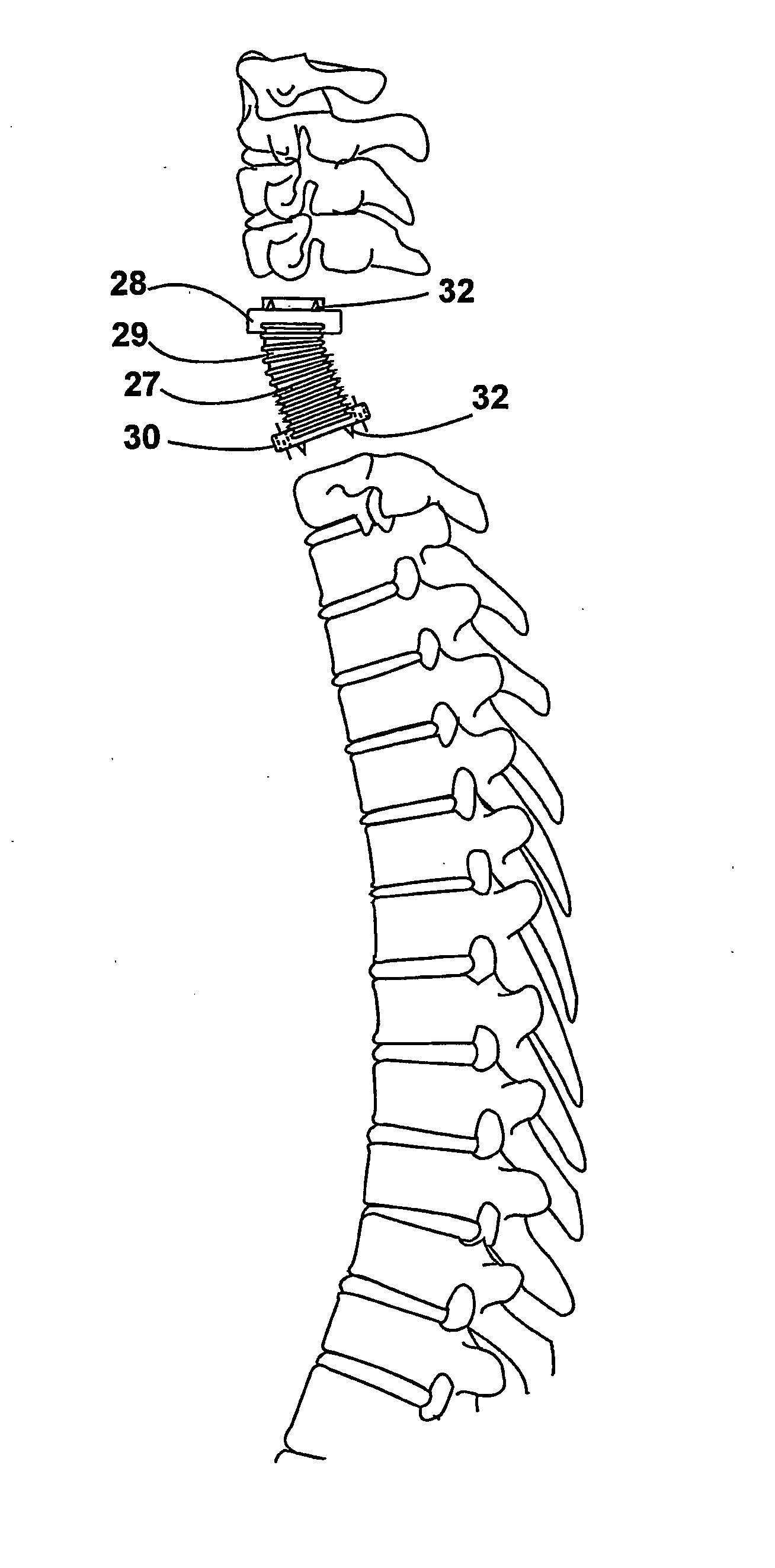
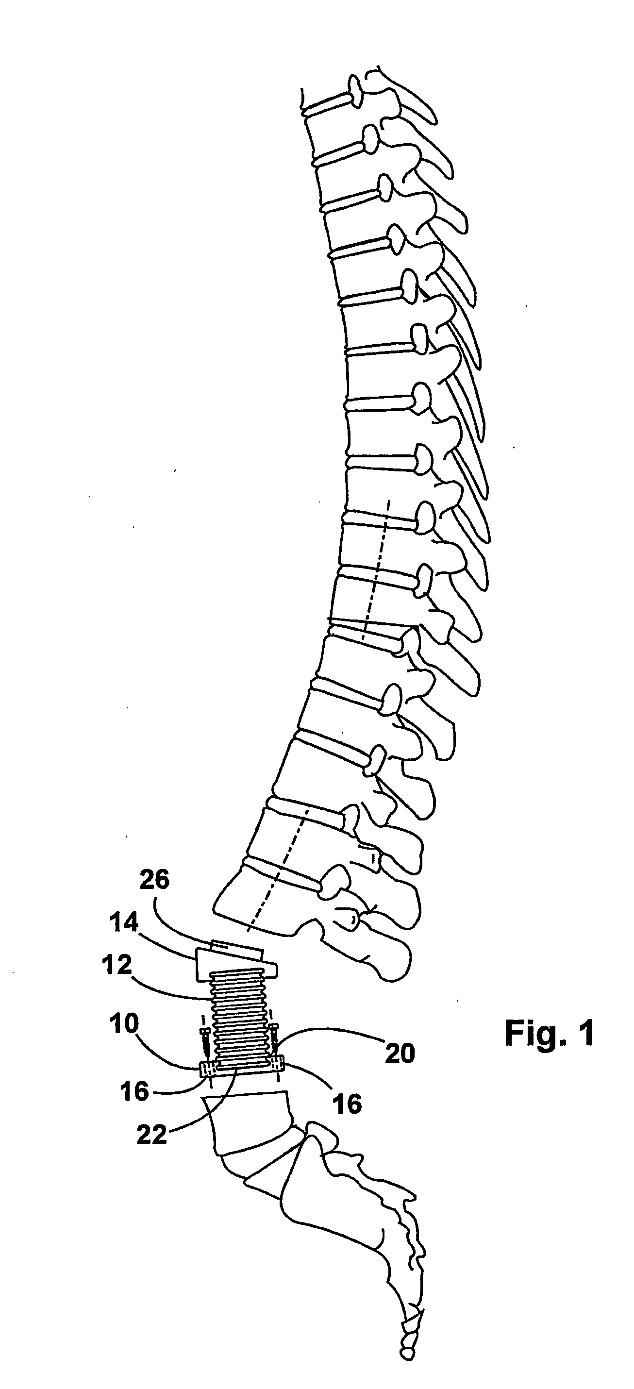
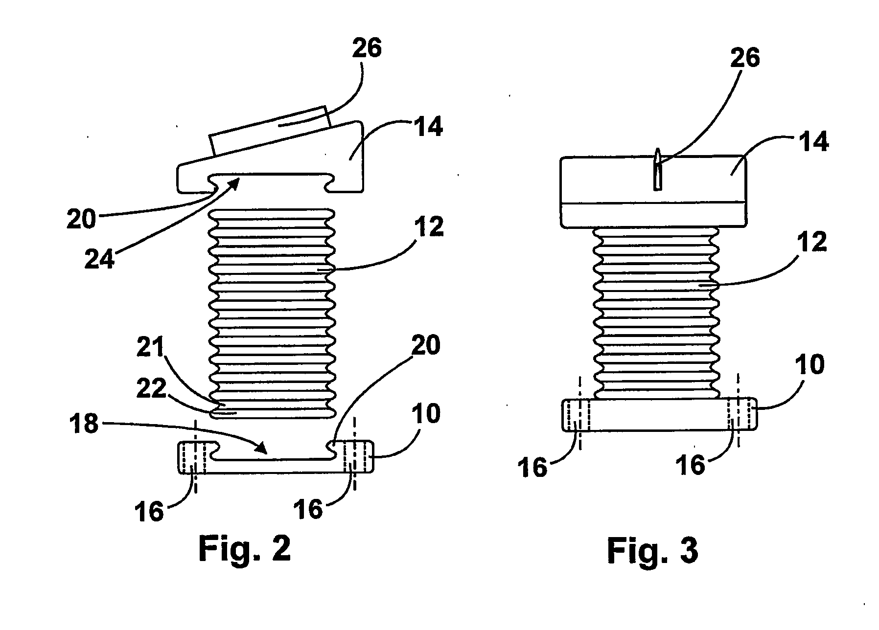
[0033]a device of the invention suitable for implantation into a human or animal spine as illustrated in the FIGS. 1 through 3 includes a base carrier 10 made of a rigid material, an elastic element configured to be an undulated bellows 12 and a top carrier 14. As best shown in FIG. 2, there are provided on the base carrier openings 16 for receiving a bone screw by means of which the base carrier 10 is fastened to the vertebral body. The bone screw is manufactured from a biomaterial that is slowly resorbed over time by the body, with the top carrier 14 and the base carrier 10 having become firmly secured to the vertebral body in the meantime.

[0034]The metallic undulated bellows 12 comprises an undulated outer contour, with discrete undulation troughs 21 and crests 22 annularly surrounding the undulated bellows 12. This undulated bellows 12 resembles for example an accordion hose. The base carrier 10 further possesses, on its side turned away from the vertebral body, a receiving port...

fourth embodiment

[0045]In the fourth embodiment illustrated in the FIGS. 9 and 10, an abutment 42 against which the uppermost undulation 44 comes to rest is formed in the receiving portion 24 provided on the top carrier 40. As a result, the undulated bellows 46 can be accurately positioned and mounting is facilitated since the surgeon is now capable of inserting the undulated bellows 46 into the top carrier 40 or into the base carrier 48 without having to care for other details. The abutment 42 is thereby implemented as a side wall of the top carrier 40 and possesses a receiving portion 24 the contour of which is configured to correspond to the contour of the undulation 44.

[0046]In a receiving portion 18 provided on the base part 48, there is also implemented an abutment 42 that corresponds to the abutment 42 of the top carrier 40. The abutment 42 of the base part 48 is however disposed exactly opposite the abutment of the top carrier 40 so that the two abutments 42 are virtually confronting each ot...

fifth embodiment

[0047]In the fifth embodiment illustrated in the FIGS. 11 and 12, two radially protruding pins 56, 58 are formed on a respective one of the uppermost and lowermost undulations 52, of the undulated bellows 50, said pins being insertable into corresponding recesses 60, 62 provided in the top carrier 64 and in the base carrier 66 respectively. The pins 56, 58 cooperate with the recesses 60, 62 to form a bayonet connection. This bayonet connection allows for fast and easy insertion of the undulated bellows 50 into the top carrier 64 or into the base carrier 66, with the pins 56, 58 being inserted into the recesses 60, 62. By pivoting the elastic element 50, the pins 56, 58 are caused to enter deep into the L-shaped recess 60, 62 where they get jammed since the recesses are configured to have a conical taper. By causing the bayonet socket to get jammed in the conical taper of the recesses 60, 62, the undulated bellows 50 is well locked in the top carrier 64 and / or in the base carrier 66 ...


PUM

PropertyMeasurementUnit
stress forcesaaaaaaaaaa

Abstract

The invention relates to a device for implanting in a human or animal vertebral column, said device comprising a base carrier (10) that can be fixed to a first vertebral body, an upper carrier (14) that can be fixed to a second vertebral body, and a spacer element fixed between the base carrier and the upper carrier. The base carrier (10) and / or the upper carrier (14) are provided with a cavity (18, 24) comprising undercuts, for receiving the spacer element in a positively locked manner. The aim of the invention is to economically create one such device that ensures complete freedom of movement of the vertebral column. To this end, the spacer element is embodied as metallic bellows (12).

Description

[0001]DE 203 07 876.4 dated May 19, 2003BACKGROUND OF THE INVENTION[0002]1. Field of the Invention[0003]The present invention relates to a device for implantation into a human or animal spine according to the preamble of claim 1. The human spine is formed from various vertebral bodies that are separated from each other by an intervertebral disc (simply called disc in common parlance) acting as a cushion therebetween. These intervertebral discs are made up of a fibrous outer casing that contains a gelatinous liquid. The intervertebral discs are subjected to high forces that may vary from about 780 N to no less than about 2200 N. In particular with age, these high stress forces often cause wear on the intervertebral discs. A once destroyed intervertebral disc cannot heal so that damaged intervertebral discs are usually removed and the adjacent vertebral bodies fused together. The disadvantage thereof is that in this region the spine will be stiff.[0004]2. Description of the Prior Art[...

Claims


Application Information

Patent Timeline
Patent Type & Authority Applications(United States)
IPC IPC(8): A61F2/44A61B17/86A61F2/00A61F2/02A61F2/30
CPCA61B17/86A61F2/44A61F2/442A61F2002/30062A61F2002/30387A61F2002/30426A61F2220/0025A61F2002/30604A61F2002/30616A61F2002/30785A61F2002/30841A61F2002/30884A61F2210/0004A61F2002/30565
Inventor METZ-STAVENHAGEN, PETER
Owner METZ STAVENHAGEN PETER
Why Eureka
Try Eureka