Method for manufacturing reinforced rubber hose

a technology of reinforced rubber and hoses, which is applied in the field of manufacturing methods for reinforced rubber hoses, can solve the problems of insufficient post-processing technology to process the combustion gas exhausted from the engine with catalysts and the like, the demand for the shape of the bellows will be more stringent, and the difficulty of the machine molding of rubber hoses to be used for this purpose, etc., to achieve good size precision, reduce manufacturing costs, and increase productivity

Inactive Publication Date: 2010-11-25
MARUGO RUBBER IND
View PDF3 Cites 20 Cited by
  • Summary
  • Abstract
  • Description
  • Claims
  • Application Information

AI Technical Summary

Benefits of technology

[0015]According to a method for manufacturing a reinforced rubber hose of the present invention, reduction in a manufacturing cost and an increase in productivity can be realized by eliminating a manual work that requires a considerable level of skill. Moreover, a bellows-shaped reinforced rubber hose having a good size precision can be produced.

Problems solved by technology

From viewpoint of passing such strict exhaust emissions regulations, improvement in the post-processing technology to process the combustion gas exhausted from the engine with catalysts and the like will not be effective enough.
Machine molding of rubber hoses having bellows to be used for this purpose has been difficult because of the large bore, and the great depth of the bellows (the difference between the radius at the convex part and that at the concave part).
As for the air supply line to the engine, as the demand for applicability to higher temperatures and higher pressures increases, the demand on the shape of the bellows will be more stringent, making the mechanization even more difficult.
The hardest step is (c) as it requires prolonged manual work and a considerable level of skill to perform this type of manual works.
This step is not cost-effective as the tape is not reusable.
However, the manufacturing methods described in Patent Documents 1 and 2 both concern the molding by using the unvulcanized rubber hoses not having a reinforcement material.
It is difficult to form the bellows shape on the unvulcanized rubber hoses having a reinforcement material by using the manufacturing methods described in either reference.
As the unvulcanized rubber hose with a reinforcement material has a high rigidity, and thus, it is not easily expanded.
However, when the manufacturing methods described in the above-described Patent Documents are used, the movement of the hose in the lengthwise direction is restricted by the constraint of the contacting mold and therefore the formation of deep bellows shape is difficult.
This makes deformation to fit along the concave part difficult.
Also, when the manufacturing method described in Patent Document 2 is used, the unvulcanized rubber hose is first pressed against the convex part at the time of inflating the rubber hose by the introduction of the pressurized air, and therefore deformation to fit along the concave part is also difficult.

Method used


Image

  • Method for manufacturing reinforced rubber hose
  • Method for manufacturing reinforced rubber hose
  • Method for manufacturing reinforced rubber hose

Examples


example 1

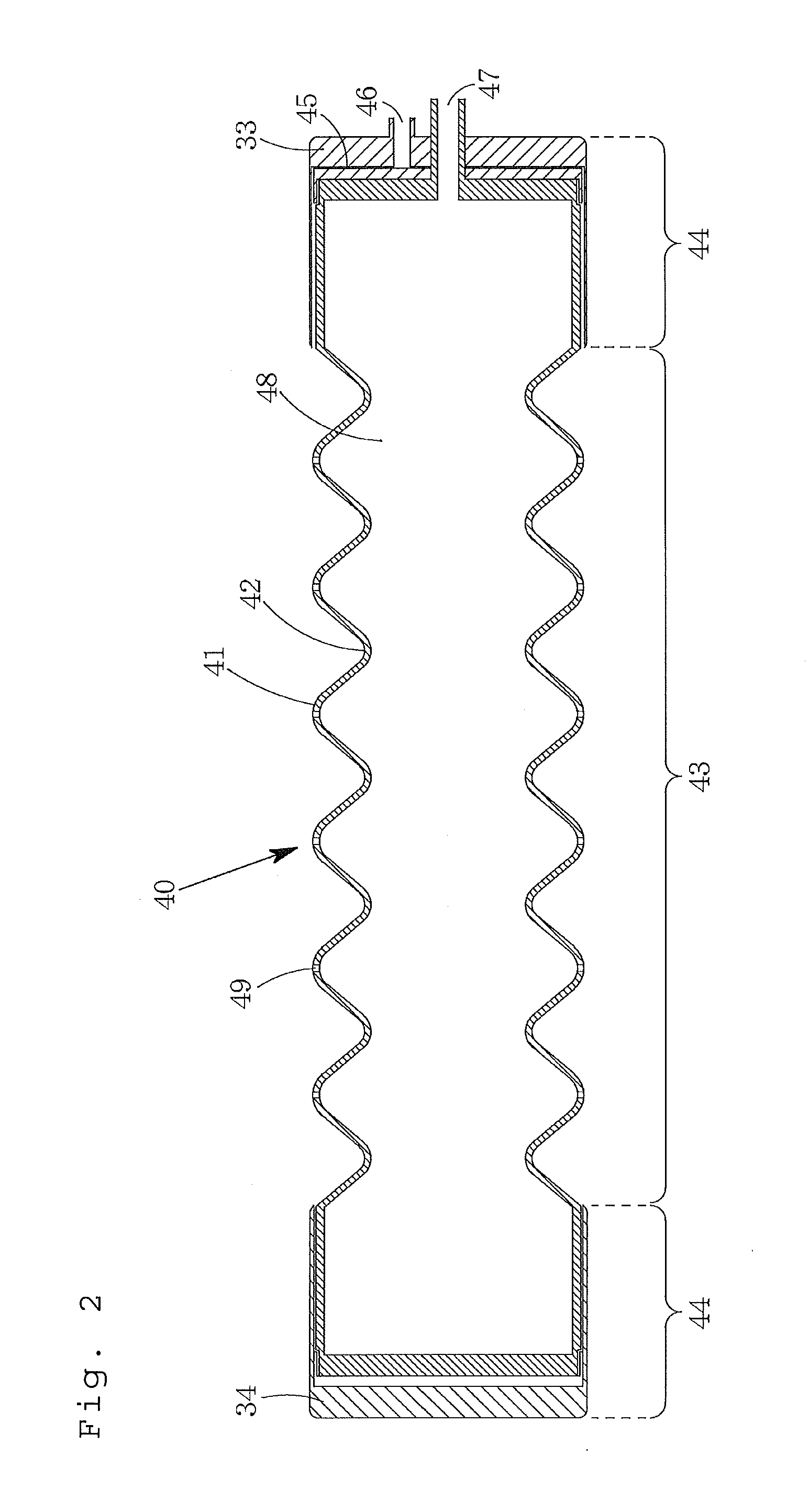
[0057]The inner mold 40 used in this example has, on its outer surface, five convex parts 41 at a height of 3 mm, formed at a pitch of 25 mm. The inner mold40 has, at the both ends, 60-mm cylindrical parts 44 having no convex or concave parts formed thereon. The inside of the inner mold 40 is hollow, and four through holes 49, 2 mm in diameter, are formed on each convex part 41.

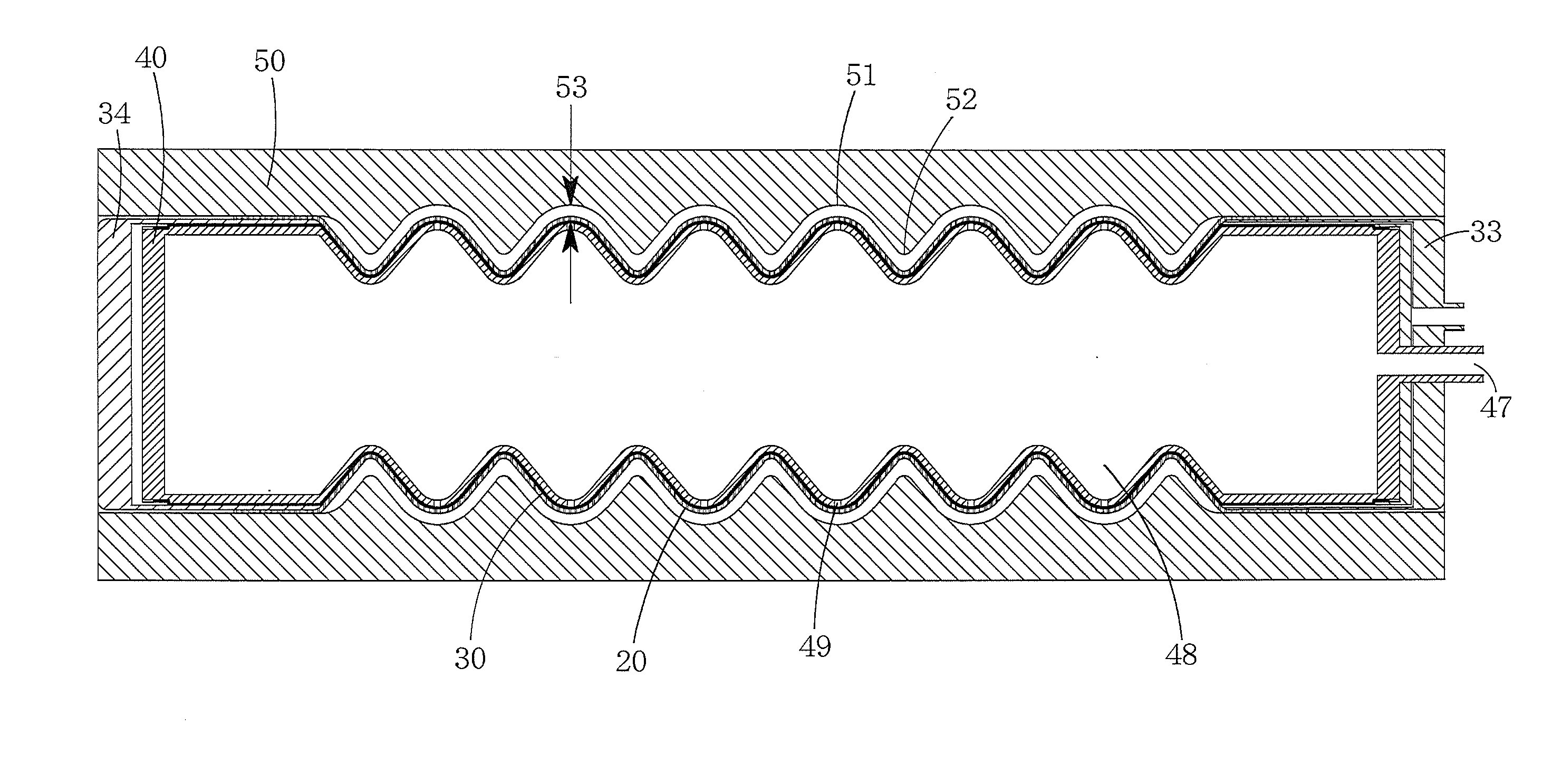
[0058]A method for preparing the airbag 30 is as follows. A 1-mm thick unvulcanized silicone rubber sheet containing a reinforcement cloth layer was wrapped around once the inner mold 40 having, on the outer surface, the corrugations matching the bellows shape. The whole body was covered with an outer mold having top and the bottom molds. The outer mold used here had an inner surface shape having a 1-mm clearance from the inner mold 40. By subsequent vulcanization, the inner mold 40 to which the airbag 30 shaped in advance in a bellows shape is attached was obtained. The airbag 30 covered the entire corrugate...

example 2

[0065]The inner mold 40 used in this example has five 6.5-mm deep convex parts 41 at a pitch of 26 mm formed on the outer surface thereof. The inner mold 40 has, at both ends, 70-mm long cylindrical parts 44 having no convex or concave parts thereon. The outer diameter of the cylindrical part 44 is 101 mm. The inside of the cylindrical part 44 is hollow and the four through holes 49, 2 mm in diameter, are formed on each convex part 41.

[0066]A method for preparing the airbag 30 is as follows. A 1-mm thick unvulcanized silicone rubber sheet containing a reinforcement cloth layer was wrapped once around the inner mold 40 having, on the outer surface, the corrugations matching the bellows shape. Then the silicone rubber sheet was covered with the outer mold having top and bottom molds. The inner surface of the outer mold used in this case is shaped to have a clearance of 1 mm from the inner mold 40. By subsequent vulcanization, the inner mold 40 to which the airbag 30 having a bellows s...

example 3

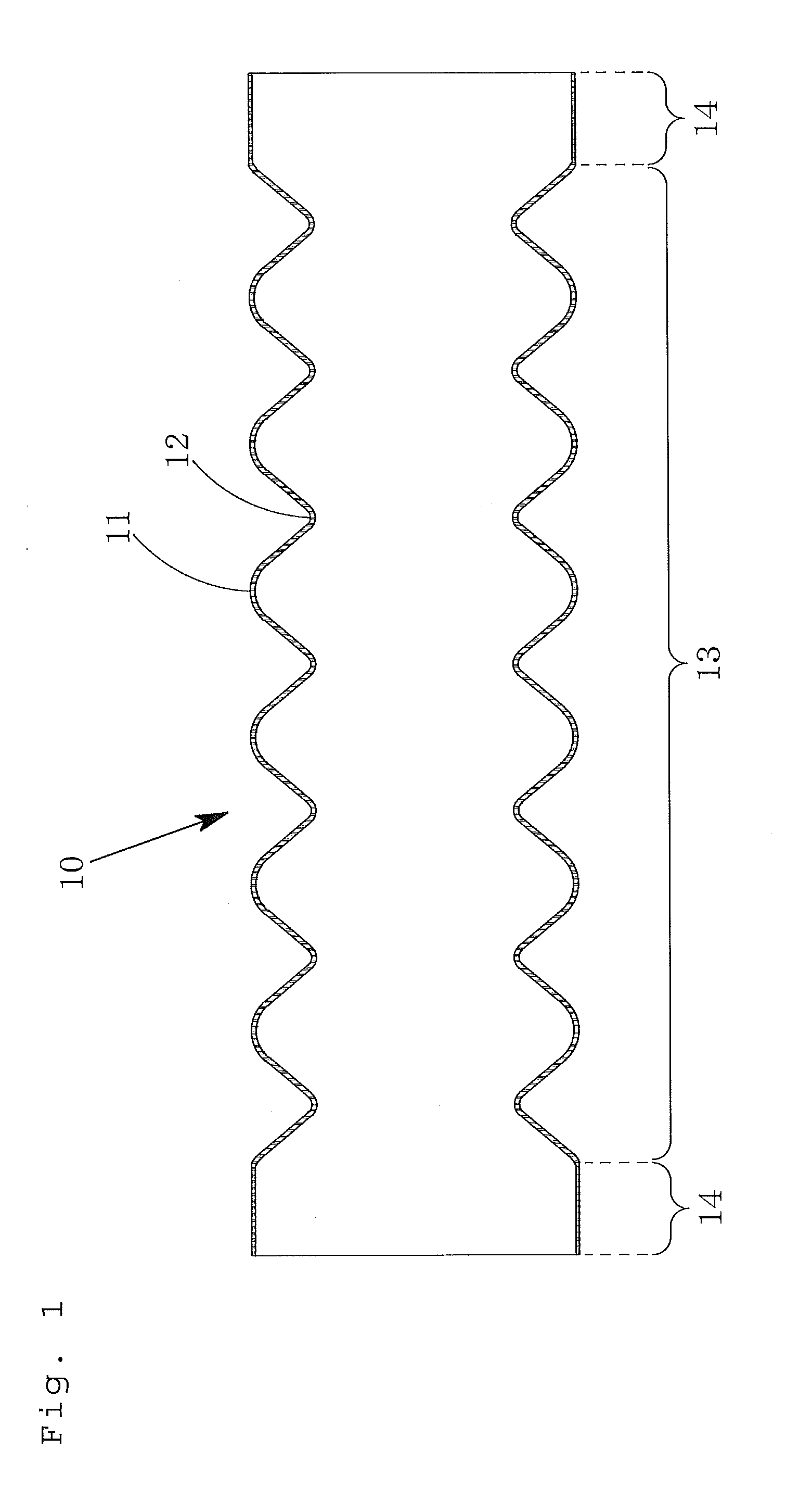
[0070]A reinforced rubber hose 10 having a bellows was obtained in the same manner as for the example 2 except that the de-pressurization formation process was not performed. That is, the example 3 was carried out similarly to the example 2 except that in this case the inner mold 40 having the airbag 30 attached thereon was inserted into the preform 20 and the inner mold 40 was immediately covered with the outer mold 50 consisting of two separate parts. The reinforced rubber hose 10 thus obtained had a total thickness of 3.6 mm at the straight tube part 14, an outer diameter of 106 mm at the convex part 11, and an outer diameter of 101 mm at the concave part 12. A height difference between the convex part 11 and the concave part 12 (the depth of the bellows) was about 2.5 mm, and the targeted bellows depth could not be obtained. In addition, the outer surface of the product around the convex part 11 of the bellows was not smooth. That is, when the de-pressurization formation process...


PUM

PropertyMeasurementUnit
depthaaaaaaaaaa
depthaaaaaaaaaa
thicknessaaaaaaaaaa

Abstract

An inner mold having, on the outer surface thereof, corrugations matching the shape of the bellows, and an outer mold having, on the inner surface thereof, corrugations matching the shape of the bellows, are used. An airbag that is previously and at least partially formed into a bellows shape is placed on an outer side of the inner mold so as to cover at least a corrugated part with the airbag. A cylindrical preform comprising unvulcanized rubber and a reinforcement material is placed on the outer side of the airbag. An outer mold is placed on the outer side of the preform. A pressurized fluid is supplied between the inner mold and the airbag so as to inflate the airbag. The preform is vulcanized under heating while being pressed against an inner surface of the outer mold, whereby a reinforced rubber hose is manufactured.

Description

TECHNICAL FIELD[0001]The present invention relates to a method for manufacturing a reinforced rubber hose having bellows. In particular, the present invention relates to a method for manufacturing a reinforced rubber hose suitable for use in automobiles as an intercooler hose, a retarder hose, or a radiator hose.BACKGROUND ART[0002]Recently, exhaust emissions regulations of diesel-powered vehicles have become more and more stringent each year. New short-term exhaust emissions regulations became effective in 2003 to 2004, new long-term exhaust emissions regulations became effective in 2005, and in addition, the enforcement of post new long-term exhaust emissions regulations is scheduled in 2009 to 2010. From viewpoint of passing such strict exhaust emissions regulations, improvement in the post-processing technology to process the combustion gas exhausted from the engine with catalysts and the like will not be effective enough. Improvement of the combustion condition in the engine it...

Claims


Application Information

Patent Timeline
Patent Type & Authority Applications(United States)
IPC IPC(8): B29D23/18
CPCB29C33/505Y02T10/14B29C53/30B29C53/38B29C53/562B29D23/18B29K2021/00B29K2105/246B29L2023/18B29L2031/703F16L11/111F16L11/112F02M35/10301F02M35/10321F02M35/10354B29C35/04Y02T10/12
Inventor FUJIKI, SOHEIMIYAKE, TAKASHIYASUMATSU, HIFUMIOHGA, SHIGETOFUJIWARA, YASUAKIBABA, TOSHIHIROYAMAKAWA, HARUKANOBUHARA, HIROSHI
Owner MARUGO RUBBER IND
Why Eureka
Try Eureka