Check patentability & draft patents in minutes with Patsnap Eureka AI!

Optical fiber sensor

Inactive Publication Date: 2010-11-25
MITSUBISHI ELECTRIC CORP
View PDF6 Cites 18 Cited by
  • Summary
  • Abstract
  • Description
  • Claims
  • Application Information

AI Technical Summary

Benefits of technology

[0011]According to the present invention, a variation amount of the received light intensity can be increased relative to a refractive-index fluctuation of the target, so that the sensitivity of the sensor can be increased.

Problems solved by technology

Pure gasoline used as automobile-engine fuel includes light gasoline including a hydrocarbon, as a main component, such as heptane and pentane, heavy gasoline including that, as a main component, such as benzene, and their intermediate medium gasoline (normal regular gasoline); therefore, if an ignition timing, etc., is not dully controlled corresponding to the characteristics of the gasoline, deterioration of driving performance or increase of harmful components included in the exhaust gas will occur.

Method used


Image

  • Optical fiber sensor
  • Optical fiber sensor
  • Optical fiber sensor

Examples


embodiment 1

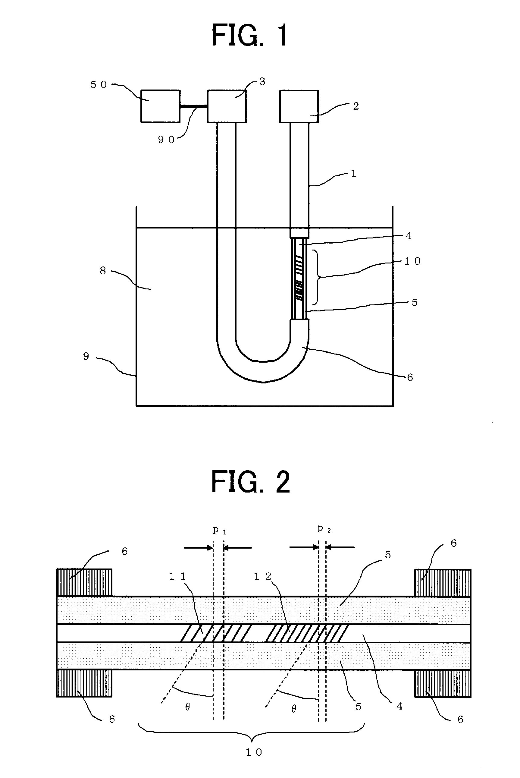
[0054]FIG. 1 is a schematic diagram explaining an optical fiber sensor according to Embodiment 1 implementing the present invention. In FIG. 1, a light source 2 is arranged at one end portion of an optical fiber 1, and a light receiving unit 3 is arranged at the other end portion. The optical fiber 1 is provided with a core 4 through which light mainly from the light source 2 propagates, a cladding 5 covering the core 4 so that light is confined in the core 4, and a fiber jacket 6 which covers and protects the cladding 5. A part of the fiber jacket 6 is removed so that the cladding 5 directly contacts a liquid target 8 to be measured, and short-period gratings 10 are formed on the core 4 corresponding to the portion from which the fiber jacket 6 is removed. The optical fiber sensor is configured with the optical fiber 1, the light source 2, the light receiving unit 3, and a refractive-index calculation unit 50 connected to the light receiving unit 3 through a signal line 90. The opt...

embodiment 2

[0083]The effect of the provision of the short-period gratings 10 having the periods different from each other has been explained in Embodiment 1. In this embodiment, an optical fiber sensor is explained that has a plurality of the short-period gratings 10 whose periods as well as tilt angles are different from each other.

[0084]First, a dependency of the refractive index of the target 8 against the tilt angle of the short-period grating 10 is explained. By changing the period of the short-period grating 10 as explained in Embodiment 1, the wavelength range where the transmission loss appears under cladding propagation mode can be shifted; however, the measurable range of refractive-index of the target 8 to be measured does not vary. In contrast, by changing the tilt angle of the short-period grating 10, it is possible to vary the measurable range of refractive-index of the target 8 to be measured, as well as to shift the wavelength range where the cladding-propagation-mode transmiss...

embodiment 3

[0110]In the short-period grating 10 of the optical fiber sensor according to this embodiment, a region in which the refractive index is different from that of the core 4 is not planarly formed, but is curvedly provided. Hereinafter, such a short-period grating 10 is referred to as short-period grating 10 tilted with a continuously varying angle.

[0111]First, an explanation will be made for the optical fiber 1 represented in Embodiments 1, in which the tilt angle of the short-period grating 10 is uniform, that is, the region in which the refractive index is different from that of the core 4 is formed planarly.

[0112]The short-period grating 10 having a constant tilt angle is formed, for example, using periodical linear beams 30, having the wavelength of 266 nm, of the fourth harmonic wave from an Nd-YAG laser having the output power of 200 mW, by irradiating a multi-mode quartz optical fiber 1 whose fiber jacket 6 has been removed, with the linear beams 30 tilted by a predetermined an...


PUM


Abstract

An objective of the present invention is to provide an optical fiber sensor which has a simple configuration to enable sensitively measuring a refractive index of a measurement medium in a wide range of refractive indexes. An optical fiber sensor according to the present invention includes; an optical fiber having a core in which a short-period gratings are formed and a cladding, the optical fiber being made so that transmission loss occurs due to cladding-propagation-mode leakage at its cladding portion where the short-period gratings are formed; a light source from which light having a wavelength range of the cladding propagation mode is emitted; and a light receiving unit for receiving transmission or reflection light having passed through the cladding at the position where the short-period gratings are formed. The optical fiber sensor detects, based on the total receiving light intensity that the light receiving unit receives, the refractive index of the measurement medium contacting the cladding, in which the optical fiber is multi-mode one, and the short-period gratings have plural kinds of periods.

Description

TECHNICAL FIELD[0001]The present invention relates to an optical fiber sensor, especially relates to an optical fiber sensor for detecting liquid characteristics by utilizing a refractive index.BACKGROUND ART[0002]Pure gasoline used as automobile-engine fuel includes light gasoline including a hydrocarbon, as a main component, such as heptane and pentane, heavy gasoline including that, as a main component, such as benzene, and their intermediate medium gasoline (normal regular gasoline); therefore, if an ignition timing, etc., is not dully controlled corresponding to the characteristics of the gasoline, deterioration of driving performance or increase of harmful components included in the exhaust gas will occur.[0003]In the USA and in European countries, in order to reduce the amount of petroleum oil consumption, fuel of gasoline mixed with alcohol becomes popular for automobiles, so that, by controlling the air-fuel ratio and the ignition timing corresponding to the alcohol content...

Claims


Application Information

Patent Timeline
IPC IPC(8): G01N21/41
CPCG01D5/35383G02B6/02085G01N2021/433G01N21/431G01D5/35316
Inventor NISHIKAWA, SATOSHITAKABAYASHI, MASAKAZUYAGYU, EIJIYOSHIARA, KIICHIMITANI, TATEKIHAMATANI, YUTAROU
Owner MITSUBISHI ELECTRIC CORP
Features
  • R&D
  • Intellectual Property
  • Life Sciences
  • Materials
  • Tech Scout
  • Unparalleled Data Quality
  • Higher Quality Content
  • 60% Fewer Hallucinations
Learn More