Plastic component with diamond-like carbon layer
a technology of carbon layer and plastic component, applied in the field of plastic components, can solve the problems of poor corrosion resistance of plastic products, plastic products usually do not do justice to attracting consumers,
- Summary
- Abstract
- Description
- Claims
- Application Information
AI Technical Summary
Benefits of technology
Problems solved by technology
Method used
Image

Examples
second embodiment
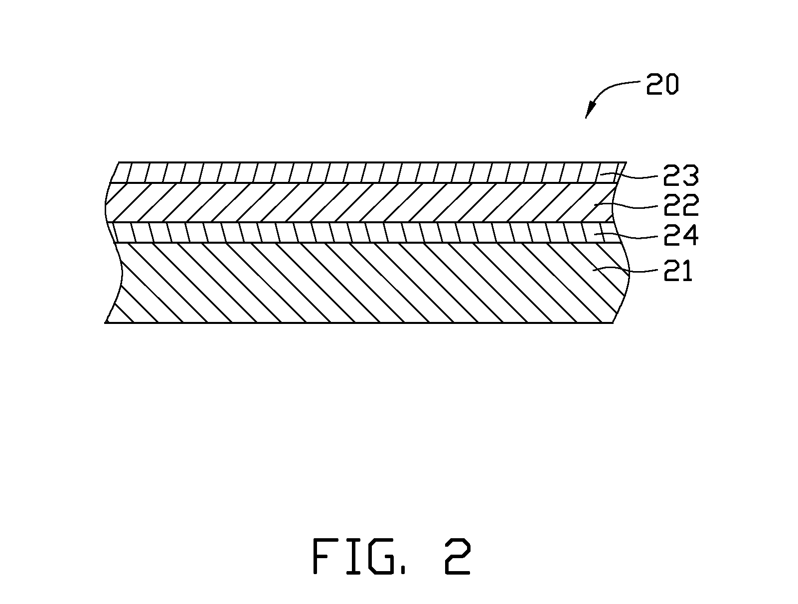
[0018]Referring to FIG. 2, the plastic component 20 includes a polymer base 21, an intermediate layer 24, a metallic luster layer 22, and a DLC layer 23 formed in sequence. A material of the polymer base 21 can be selected from the group consisting of PC, PP, ABS, PMMA, and a combination thereof.
[0019]The intermediate layer 24 is interposed between and in contact with both of the polymer base 21 and the metallic luster layer 22. The intermediate layer 24 is comprised of chromium nitride (CrN), chromium carbide (CrC), or chromium dioxide (CrO2). In particular, the intermediate layer 24 can consist essentially of CrN, CrC, or CrO2. A thickness of the intermediate layer 24 is in the range from 2 nm to 10 nm. Due to such a thickness of the intermediate layer 24, the phases of the intermediate layer 24 in microstructure are discontinuous, thus that the intermediate layer 24 is dielectric. It is understood that the intermediate layer 24 also can be formed by sputtering technology.
[0020]Th...
third embodiment
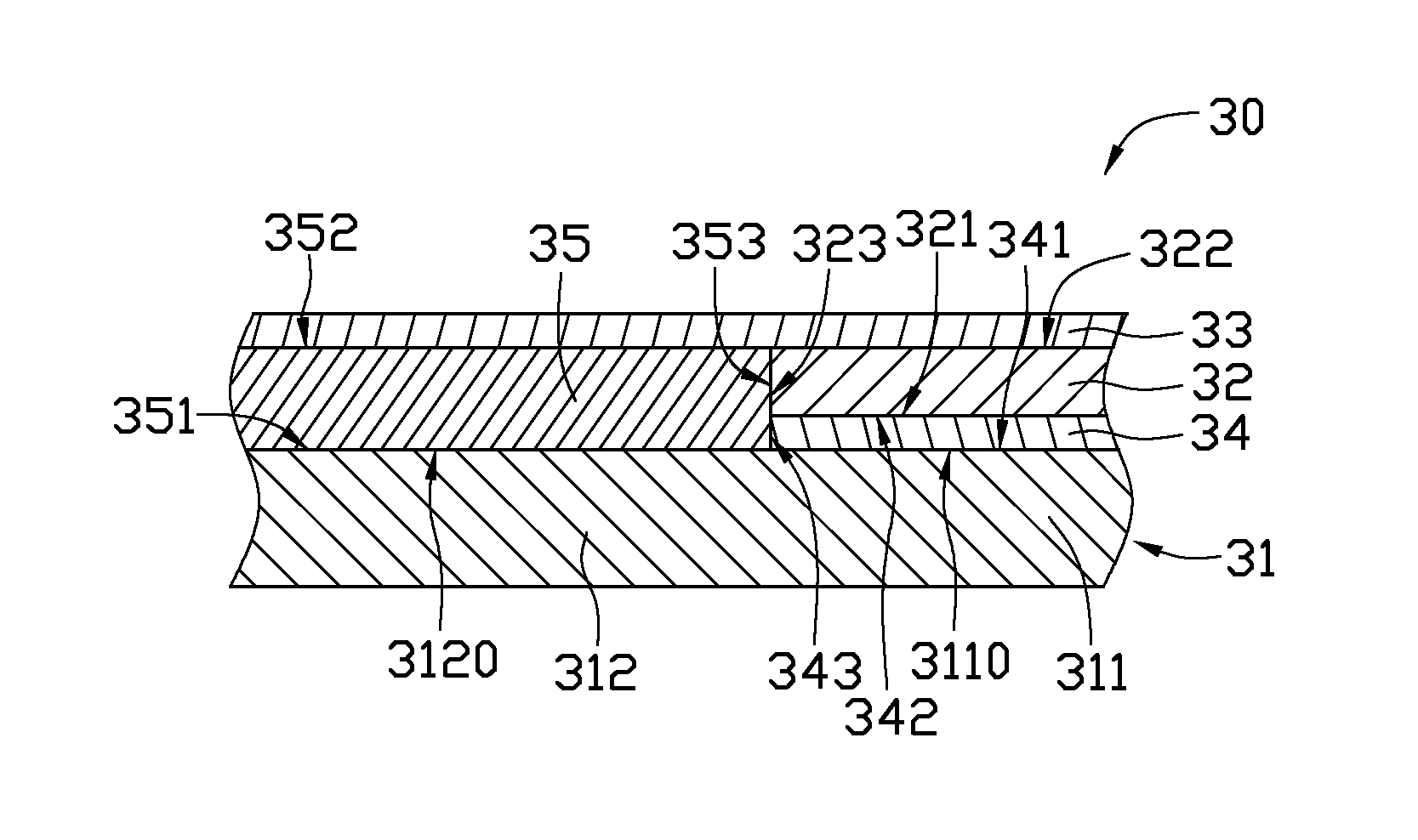
[0022]Referring to FIG. 3, the plastic component 30 includes a polymer base 31, an intermediate layer 34, an electrically conductive layer 35, a metallic luster layer 32, and a DLC layer 33. The polymer base 31 has a first portion 311 and a second portion 312 proximate to the first portion 311. The first portion 311 has a first outer surface 3110. The second portion 312 has a second outer surface 3120, which is coplanar with the first outer surface 3110. The intermediate layer 34 is formed on the first outer surface 3110 of the first portion 311. The metallic luster layer 32 is formed on the intermediate layer 34. The electrically conductive layer 35 is formed on the second outer surface 3120 of the second portion 312, and comprises of chromium, aluminum, or any other suitable electrically conductive material. In particular, the electrically conductive layer 35 can be chromium layer or aluminum layer. A thickness of the electrically conductive layer 35 is equal to a sum of thickness...
fourth embodiment
[0025]Referring to FIG. 4, the plastic component 40 includes a polymer base 41, an electrically conductive layer 45, a metallic luster layer 42, and a DLC layer 43. The polymer base 41 includes a first portion 411 and a second portion 412 proximate to the first portion 411. The metallic luster layer 42 is arranged between and in contact with the first portion 411 and the DLC layer 43. The electrically conductive layer 45 is arranged between and in contact with the second portion 412 and the DLC layer 43. The metallic luster layer 42 has a thickness equal to that of the electrically conductive layer 45.
[0026]The polymer base 41, the electrically conductive layer 45, the metallic luster layer 42, and the DLC layer 43 have material and structure similar to that of the polymer base 31, the electrically conductive layer 35, the metallic luster layer 32, and the DLC layer 33 of the third embodiment, respectively.
PUM
| Property | Measurement | Unit |
|---|---|---|
| thickness | aaaaa | aaaaa |
| thickness | aaaaa | aaaaa |
| thickness | aaaaa | aaaaa |
Abstract
Description
Claims
Application Information
 - R&D
- Intellectual Property
- Life Sciences
- Materials
- Tech Scout
- Unparalleled Data Quality
- Higher Quality Content
- 60% Fewer Hallucinations
Browse by: Latest US Patents, China's latest patents, Technical Efficacy Thesaurus, Application Domain, Technology Topic, Popular Technical Reports.
© 2025 PatSnap. All rights reserved.Legal|Privacy policy|Modern Slavery Act Transparency Statement|Sitemap|About US| Contact US: help@patsnap.com