
Method, Apparatus, And System For Computer-Aided Tracking, Navigation And Motion Teaching

Active Publication Date: 2010-11-25
CARNEGIE MELLON UNIV
View PDF15 Cites 130 Cited by
  • Summary
  • Abstract
  • Description
  • Claims
  • Application Information

AI Technical Summary

Benefits of technology

[0014]The present invention is directed generally to methods, apparatuses, and systems for computer-aided navigation, tracking, and motion teaching. There are many applications and embodiments of the present invention. In some embodiments, the present invention may be used to ease the difficulty associated with arthroscopic hip surgery. While arthroscopic surgery has many advantages over traditional surgery, this minimally invasive technique is not often applied to the hip joint. Two main reasons for this are the complexity of navigating within the joint and the difficulty of correctly placing portal incisions without damaging critical neurovascular structures. The present invention discloses a computer-aided navigation system to address the challenges of arthroscopic hip surgery. Unlike conventional arthroscopic methods, the present invention uses a hyper-redundant tracking device to track surgical instruments, thus eliminating the occlusion and distortion problems associated with standard optical and electromagnetic tracking systems. In such embodiments, a tracking device of encoders may be employed to track the motion of surgical tools during an operation, and produce computer generated images of real-time motion of the tools relative to the patient anatomy. In this way the present invention can be used to supplement the restricted view from a typical arthroscopic camera. Ultimately, the proposed computer-aided navigation system can increase the use of advantageous arthroscopic procedures over full-incision operations in the hip joint.
[0015]In other embodiments, the present invention may be used for biopsies and to create images of targeted areas. For example, the present invention may be used with an ultrasound device to scan an area and to create two-dimensional and three-dimensional images. Thereafter, for example, the present invention may be used with a medical device, such as a biopsy needle, to create a computer generated image of the medical device (e.g., biopsy needle) in the two-dimensional or three-dimensional image created with the ultrasound device. In this way, the present invention allows the user to view a computer generated image of the medical device being used in an area (such as within the body) that is not visible. For example, the present invention may be used to navigate a biopsy needle to a target tissue region more quickly and accurately.
[0017]The present invention addresses problems in the prior art and is an effective alternative to more expensive and often problematic prior art tracking systems. For example, some prior art device rely on optical communications and, therefore require a clear line of sight for proper operation. In other prior art solutions, the devices are affected by metal objects which can interfere with electromagnetic communications systems used by the prior art. In other prior art devices, the range of motion is limited and, therefore, the device cannot reach all target locations. This is particularly problematic in prior art devices operating in an enclosed space or in the presence of barriers and obstacles. The present invention, however, overcomes these drawbacks with the prior art, as will be discussed in more detail hereinbelow. For example, some embodiments of the present invention use a combination of articulated links having six or more degrees of freedom that provide improved flexibility for maneuvers while tracking instrument position.

Problems solved by technology

While arthroscopic surgery has many advantages over traditional surgery, this minimally invasive technique is not often applied to the hip joint.
Two main reasons for this are the complexity of navigating within the joint and the difficulty of correctly placing portal incisions without damaging critical neurovascular structures.
In other prior art solutions, the devices are affected by metal objects which can interfere with electromagnetic communications systems used by the prior art.
In other prior art devices, the range of motion is limited and, therefore, the device cannot reach all target locations.
This is particularly problematic in prior art devices operating in an enclosed space or in the presence of barriers and obstacles.

Method used


Image

  • Method, Apparatus, And System For Computer-Aided Tracking, Navigation And Motion Teaching
  • Method, Apparatus, And System For Computer-Aided Tracking, Navigation And Motion Teaching
  • Method, Apparatus, And System For Computer-Aided Tracking, Navigation And Motion Teaching

Examples


Embodiment Construction

[0044]The present invention is directed generally to methods, apparatuses, and systems for computer-aided tracking, navigation, and motion teaching. The present invention has many applications, such as in medical care and in industrial manufacturing, as well as in other fields. The present invention has many specific applications, such as tracking medical tools in the body during medical procedures, generating images of medical tools in the body during medical procedures, in robot teaching, in process simulation, in path planning, and in other applications.

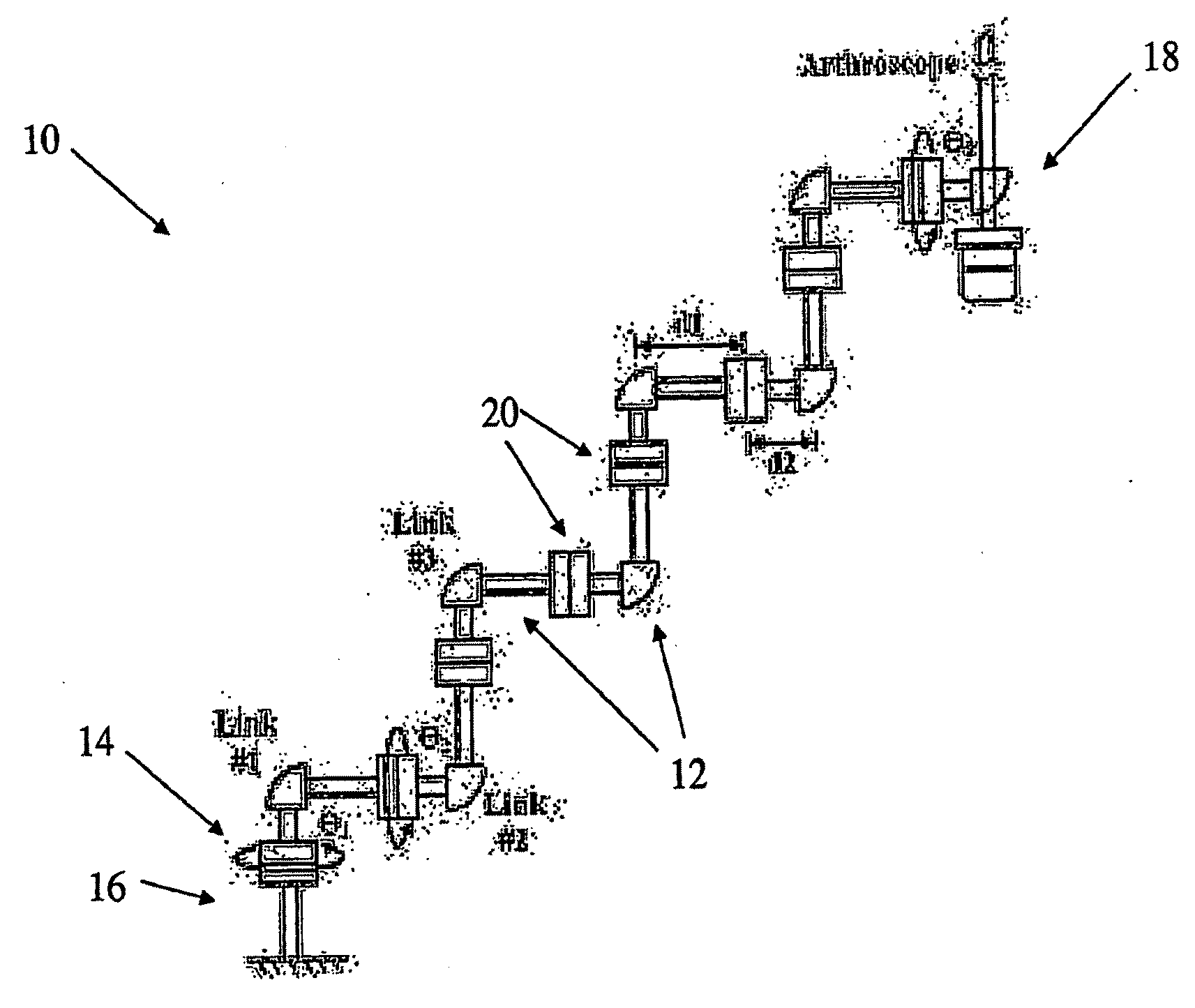
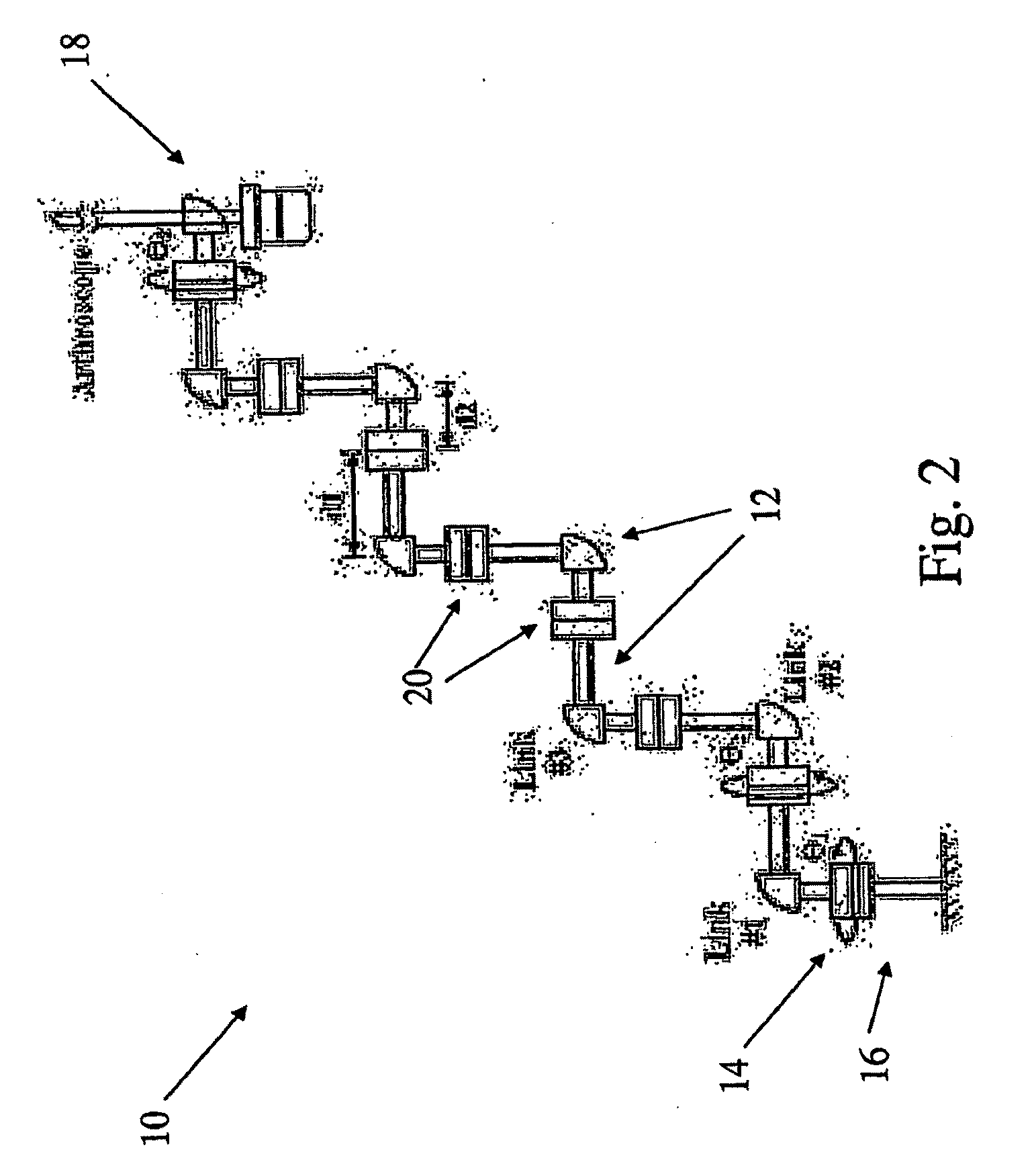
[0045]FIG. 2 illustrates one embodiment of a tracking device 10 according to the present invention. The tracking device 10 includes a plurality of links 12 connected together. The tracking device 10 in the illustrated embodiment includes a reference end 14 connected to a reference pin or some other reference point 16, and a working end 18 for moving and / or for engaging other objects. In some embodiments, the working end 18 may be ...


PUM


Abstract

Methods, apparatuses, and systems for computer-aided tracking, navigation, and motion tracking. In one embodiment, a system for determining a spatial position, including a tracking device and a processor. The tracking devices has a working end, a reference end, a plurality of links connecting the working end to the reference end, wherein each link has at least one degree of freedom relative to an adjacent link, and a plurality of sensors measuring the orientation of the links in a plurality of degrees of freedom, wherein X is a minimum number of degrees of freedom about which information is required to define the spatial position. The processor receives information from the sensors and determine the spatial position of the working end of the tracking device relative to the reference end of the tracking device based on information from the sensors measuring Y degrees of freedom, wherein Y is greater than X.

Description

CROSS-REFERENCE TO RELATED APPLICATIONS[0001]This application claims priority from PCT patent application number PCT / US2007 / 001897, filed Jan. 24, 2007, which claims priority from U.S. Provisional Patent Application No. 60 / 761,702, filed Jan. 24, 2006, both of which are incorporated herein by reference.STATEMENT REGARDING FEDERALLY-SPONSORED RESEARCH AND DEVELOPMENT[0002]This invention was made, in part, with government support under a National Science Foundation Graduate Research Fellowship grant. The United States government may have certain rights in this invention.FIELD OF THE INVENTION[0003]The present invention is directed generally to methods, apparatuses, and systems for computer-aided tracking, navigation and motion teaching.BACKGROUND OF THE INVENTION[0004]Computer-aided tracking, navigation, and motion teaching are important tasks in a wide range of applications, including surgery and factory automation. The prior art contains technology directed to the tasks of computer-...

Claims


Application Information

Patent Timeline
IPC IPC(8): G06F15/00B25J9/00
CPCA61B19/22A61B19/26A61B19/52G09B23/28A61B2019/502A61B2019/505A61B2019/5276A61B19/5244A61B2034/102A61B90/36A61B34/20A61B34/70A61B90/50A61B2034/105A61B2090/378
Inventor SHIMADA, KENJIMONICA, EMILY
Owner CARNEGIE MELLON UNIV
Learn More