Method of converting pyrolyzable organic materials to biocarbon

a technology of organic materials and biocarbons, applied in the direction of lighting and heating apparatus, drying machines, liquid hydrocarbon mixture production, etc., can solve the problems of large charcoal production quantities at relatively low conversion efficiency of raw materials, high cost of providing a pressurized reactor controlling a non-steady state process, and the mode of operation and high cost of providing a pressurized reactor. , to achieve the effect of controlling the recovery of heavier tars

Inactive Publication Date: 2010-12-02
ALTERNA ENERGY
View PDF9 Cites 70 Cited by
  • Summary
  • Abstract
  • Description
  • Claims
  • Application Information

AI Technical Summary

Benefits of technology

[0013]One object of one embodiment of the present invention is to provide a...

Problems solved by technology

The design is dated; however, the apparatus is efficient at producing large quantities of charcoal at relatively low conversion efficiency of the raw material.
Antal further establishes that the temperature range of between 400° C. and 600° C. for the highest temperature measured in the reactor, which is a lower range of temperature experienced in earlier processes where the char is heated to higher temperatures, often above 1...

Method used


Image

  • Method of converting pyrolyzable organic materials to biocarbon
  • Method of converting pyrolyzable organic materials to biocarbon
  • Method of converting pyrolyzable organic materials to biocarbon

Examples


example 1

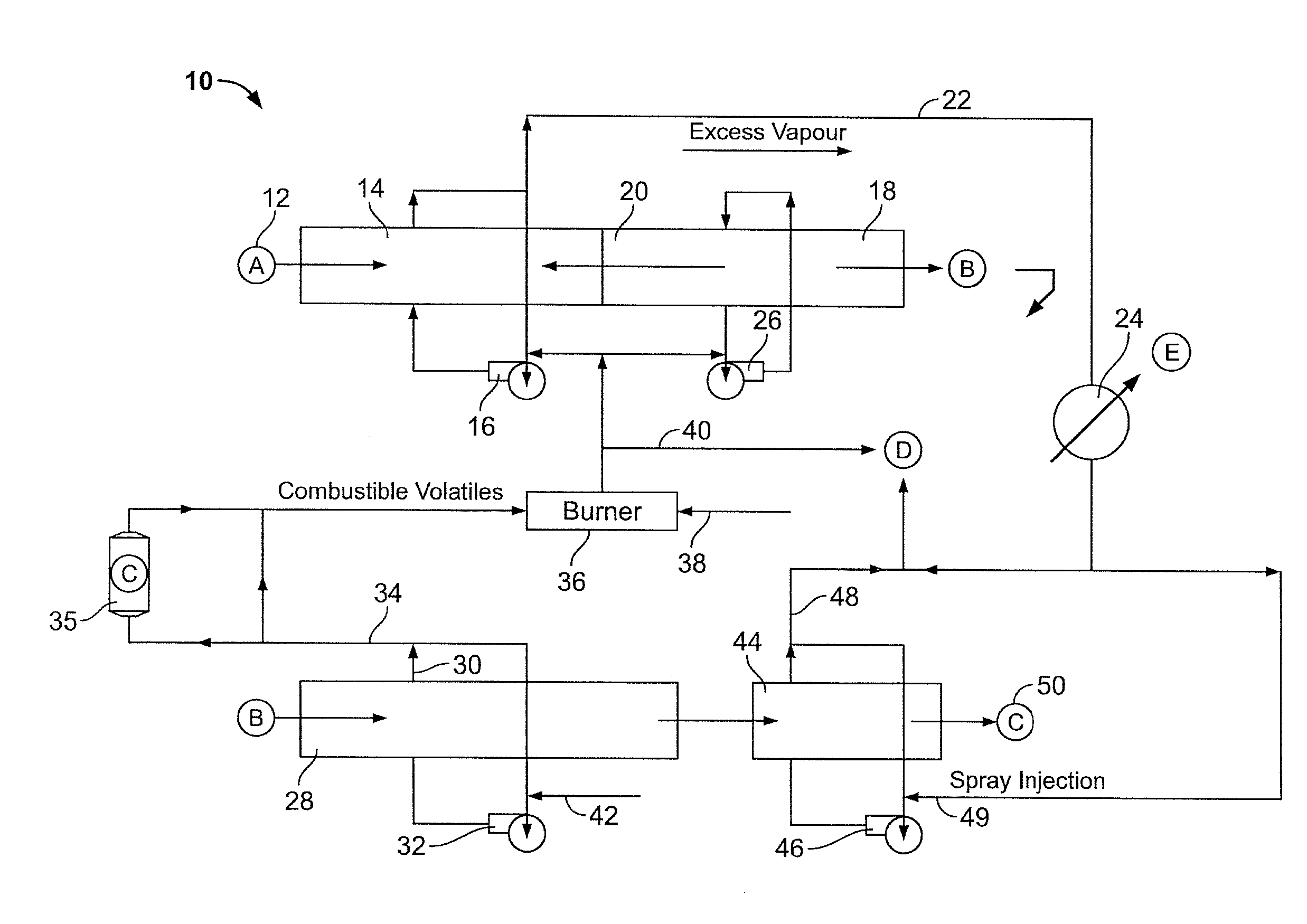
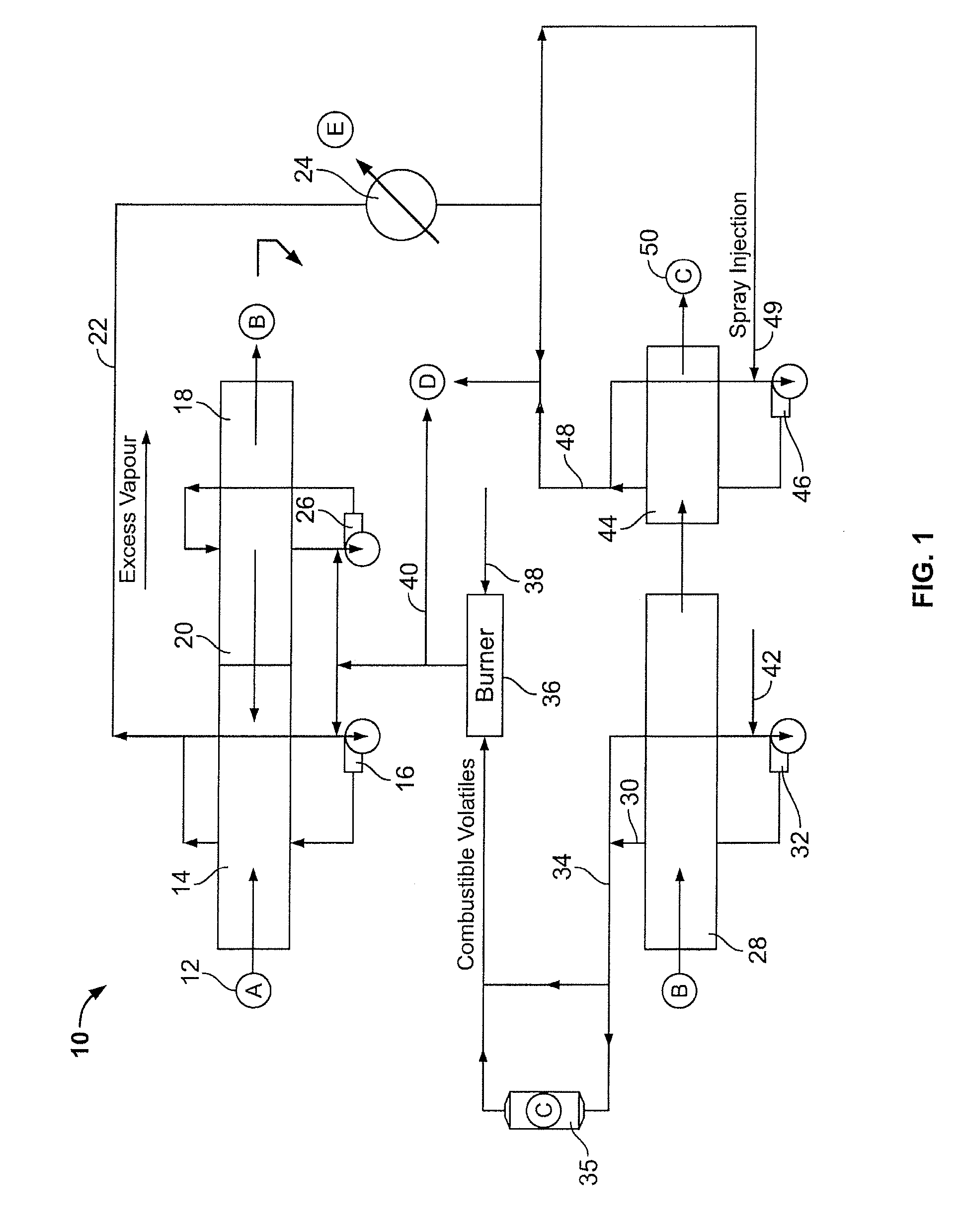
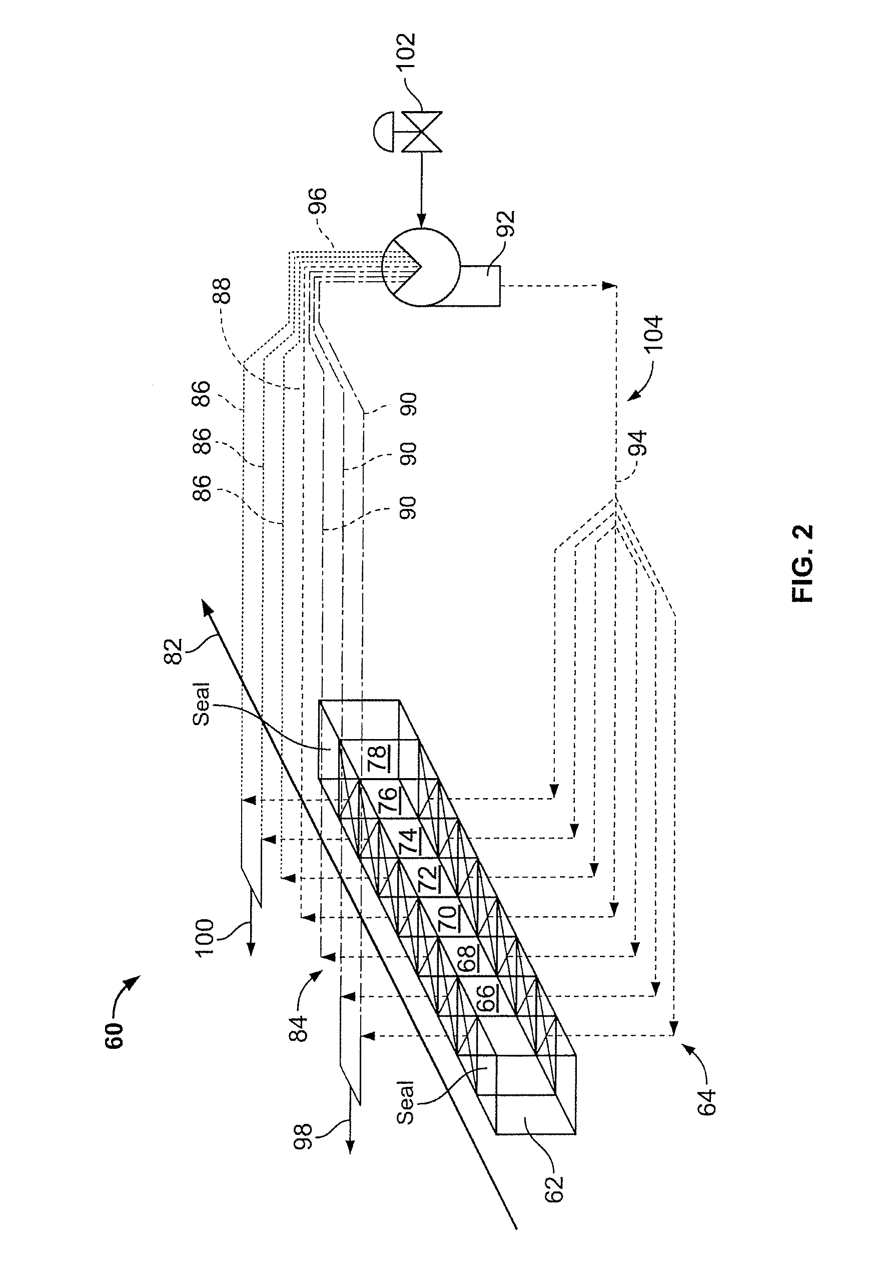
[0046]A carbonizer circuit, consisting of a drying stage, pyrolyzing stage and cooling stage, was constructed with the features described in FIG. 1 and FIG. 2. The individual bins were carbon steel boxes 40 centimeters on edge with open tops, screen bottoms and solid walls; each bin contained a nominal 65 liters of entering pyrolyzable organic material. The vapors within the carbonizer were extracted from a common plenum above all bins with a single extraction point from the common plenum above bin position 76 on FIG. 2 and returned to a common plenum under all bins with the specific return points to the common plenum being under bin position 74 and 78 on FIG. 2.

[0047]The carbonizer main fan was a large squirrel cage fan, with nominally 45-degree outward forcing fan blades. The rotating squirrel cage was 60 centimeter ID, 70 centimeter OD and 20 centimeters high. The main fan rotated at 450 rpm when driven at 60 hertz by the variable frequency drive (VFD) of the main fan. The other ...

example 2

[0049]SPF wood chips were processed by the carbonizer circuit of Example 1 with the higher temperature vapors setpoint of 350 C, as controlled by the addition of metered air prior to the carbonizer main fan. The carbonizer main fan was operated at frequencies of 30 hertz, 50 hertz and 70 hertz on the variable frequency drive (VFD) of the main fan. The push rate was typically 15 minutes, although 20 minute push intervals were used on occasion at 30 hertz to facilitate necessary heat transfer to the entering bins.

[0050]The pyrolyzing stage demonstrated improving heat exchange between the bins with increasing fan speed, as evidenced by an accelerated heating of cooler entering bins and decreased temperature gradient within the higher temperature bins. Furthermore, the yield of biocarbon product per unit of entering dry biomass increased with increasing fan speed, as measured by weighing dried coupons of wood blocks before and after carbonization. The calculated yields on a weight basis...

example 3

[0052]SPF wood chips were processed by the carbonizer circuit of Example 1 at higher temperature vapors setpoints over the range of 350 C to 425 C, as controlled by the addition of metered air prior to the carbonizer main fan. The carbonizer main fan was operated at a fixed frequency of 70 hertz on the variable frequency drive (VFD) of the main fan. The push rate was varied between runs at 15-minute push intervals and runs at 20-minute push intervals and the effect on adsorption capacity and volatile matter measured.

[0053]Independent of the higher temperature vapors setpoint over the range of 350 C to 425 C, the adsorption capacity was at least 40 percent higher in the biocarbon products produced at 20-minute push intervals as compared to the biocarbon products produced at 15-minute push intervals. In addition, the 15-minute push interval biocarbon product evidenced approximately 10 percent higher volatile matter content than the 20-minute push interval biocarbon product.


PUM


Abstract

A method of forming a pyrolysed biocarbon from a pyrolyzable organic material is delineated. The method involves the conversion of pyrolyzable organic materials to biocarbon for subsequent use. A carbonization circuit is employed with individual feedstock segments being advanced through the circuit. The method facilitates user manipulation of rate of advancement of the feedstock through the circuit, selective collation of volatiles from pyrolyzing feedstock, selective exposure of predetermined feedstock segments to collated volatiles as well as thermal recovery and redistribution as desired by the user. This results in the capacity for a customizable biocarbon product, the latter being an auxiliary feature of the methodology.

Description

FIELD OF THE INVENTION[0001]The present invention is directed to the thermal modification of pyrolyzable organic materials and more particularly, the present invention is directed to a method for converting biomass in an efficient manner into a high quality biocarbon product.BACKGROUND OF THE INVENTION[0002]Biocarbon, char, biochar or charcoal is an important compound, since the product has a number of uses, examples of which include fuel and reactant in the refining of metals. Typically, pyrolyzable organic materials are attractive progenitors for biocarbon production. Recently, new uses for biocarbons have become particularly important. One of these is the use of biocarbon for the sequestration of carbon dioxide, a greenhouse gas, and the addition to soils as an amendment to improve soil fertility. There is, given the diversity of product utilizations, a need to have efficient methods for formulating customizable types of biocarbons from pyrolyzable organic materials, such as biom...

Claims


Application Information

Patent Timeline
IPC IPC(8): C10B51/00C01B32/336
CPCC10B7/14C10B53/02C10B57/10Y02E50/14F26B23/022F26B2200/02Y02E20/12F26B15/12Y02E50/10Y02P70/10
Inventor VAN AARDT, HENDRIKMARSH, PHILMCLAUGHLIN, HUGH
Owner ALTERNA ENERGY
Why Eureka
Try Eureka