Battery thermal event detection system using a thermally interruptible electrical conductor

Active Publication Date: 2010-12-02
TESLA INC
View PDF2 Cites 20 Cited by
  • Summary
  • Abstract
  • Description
  • Claims
  • Application Information

AI Technical Summary

Benefits of technology

[0006]The present invention provides a method and apparatus for determining when a battery, or one or more batteries within a battery pack, undergoes an undesired thermal event such as thermal runaway. The system of the invention uses a conductive member mounted in close proximity to, or in contact with, an external surface of the battery or batteries to be monitored. A resistance mea

Problems solved by technology

Although rechargeable batteries offer a number of advantages over disposable batteries, this type of battery is not without its drawbacks.
In general, most of the disadvantages associated with rechargeable batteries are due to the battery chemistries employed, as these chemistries tend to be less stable than those used in primary cells.
Due to these relatively unstable chemistries, secondary cells often require special handling during fabrication.
Additionally, secondary cells such as lithium-ion cells tend to be more prone to thermal runaway than primary cells, thermal runaway occurring when the internal reaction rate increases to the point that more heat is being generated than can be withdrawn, leading to a further increase in both reaction rate and heat generation.
Thermal runaway may be initiated by a short circuit within the cell, improper cell use, physical abuse, manufacturing defects, or exposure of the cell to extreme external temperatures.
Thermal runaway is of major concern since a single incident can lead to significant property damage and, in some circumstances, bodily harm or loss of life.
When a battery undergoes thermal runaway, it typically emits a large quantity of smoke, jets of flaming liquid electrolyte, and sufficient heat to lead to the combustion and destruction of materials in close proximity to the cell.
If the cell undergo

Method used


Image

  • Battery thermal event detection system using a thermally interruptible electrical conductor
  • Battery thermal event detection system using a thermally interruptible electrical conductor
  • Battery thermal event detection system using a thermally interruptible electrical conductor

Examples


Embodiment Construction

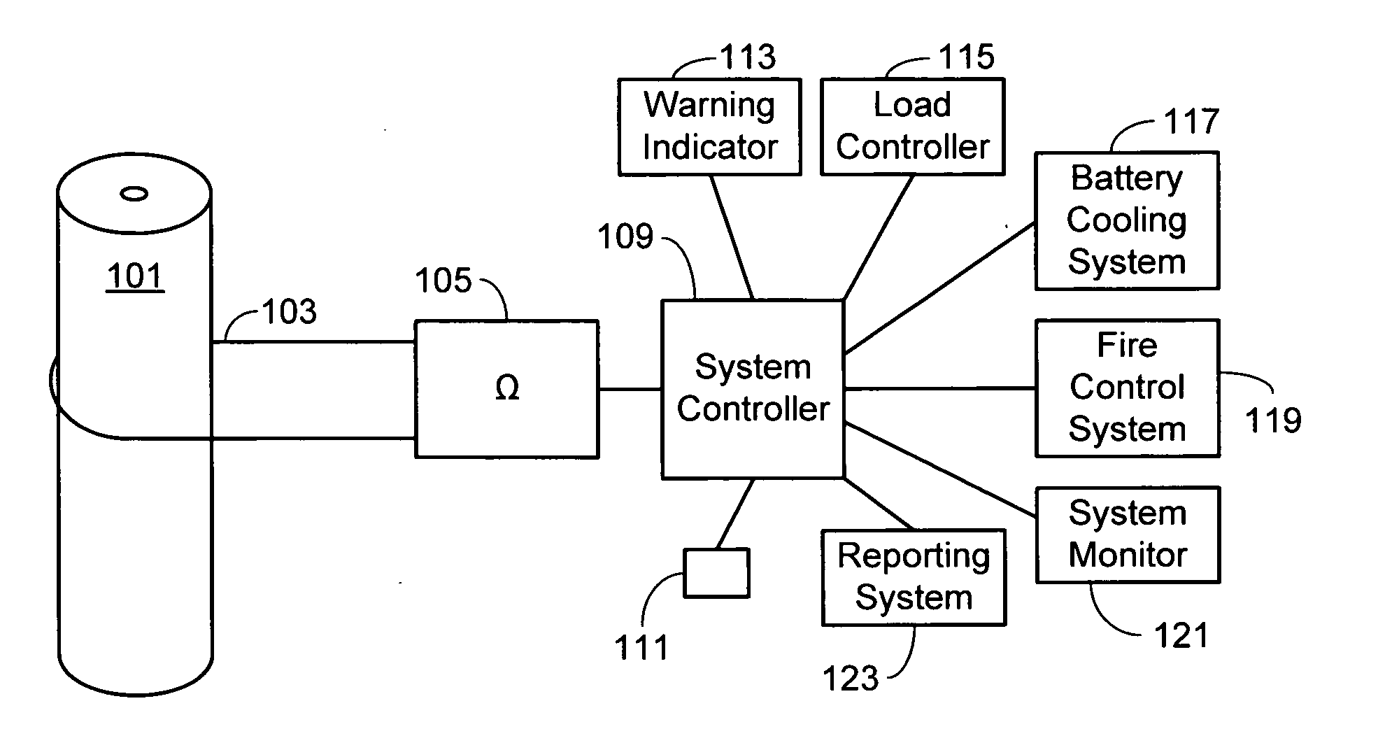
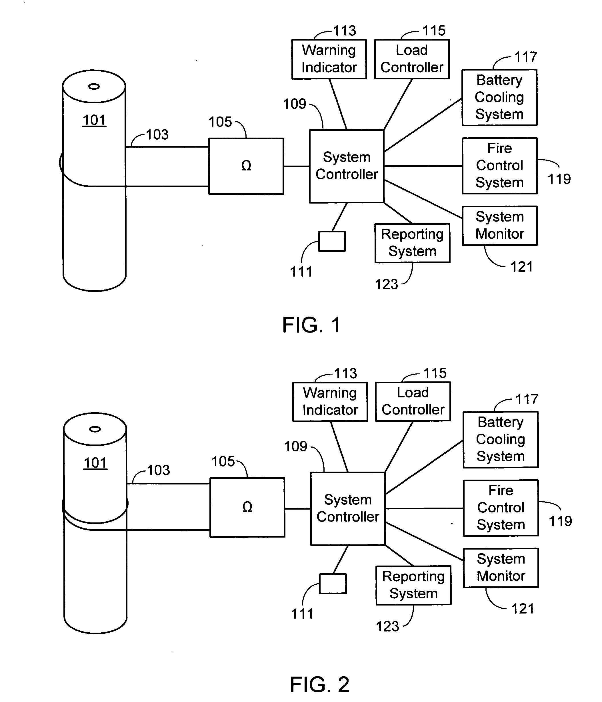
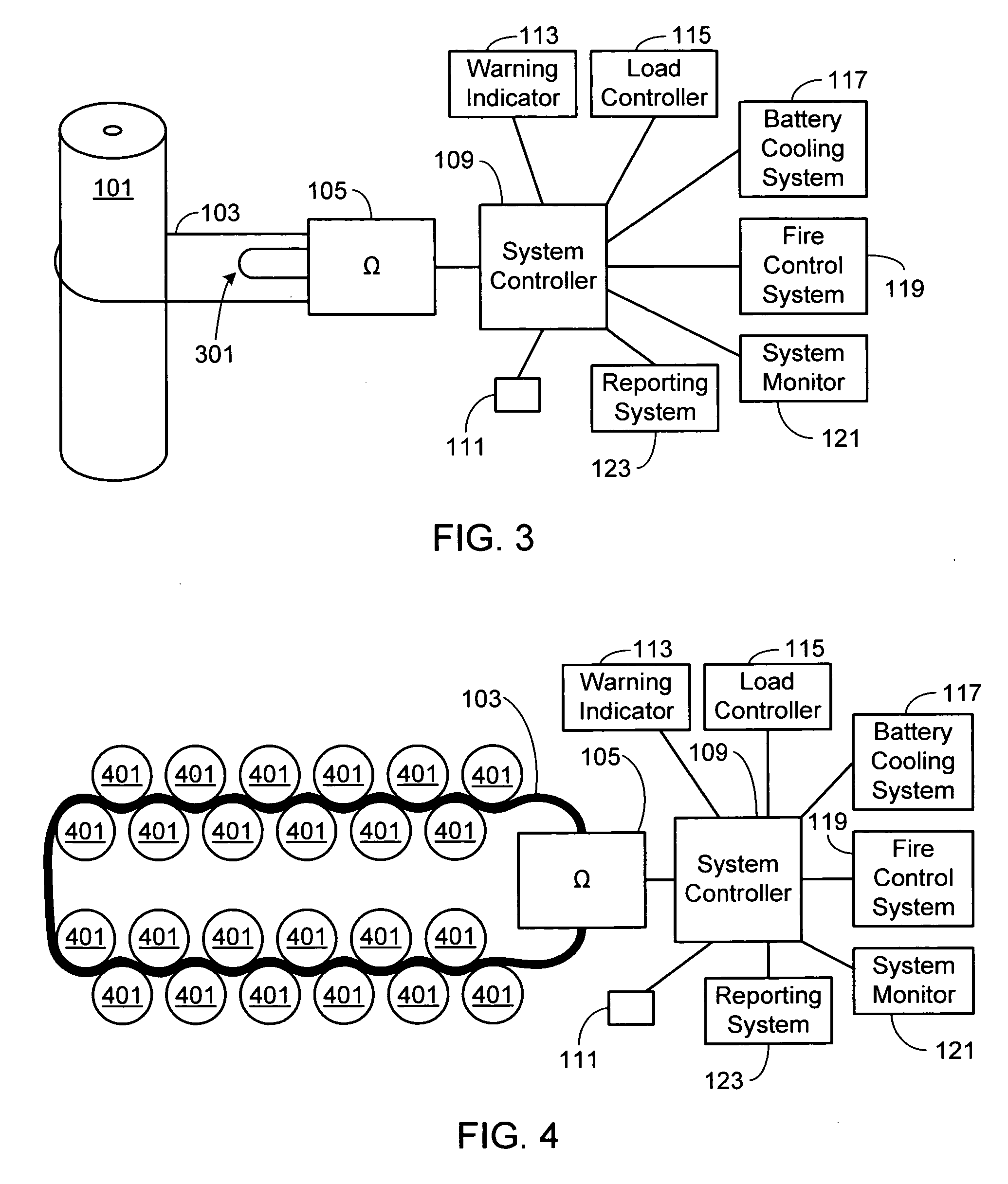
[0017]In the following text, the terms “battery”, “cell”, and “battery cell” may be used interchangeably and may refer to any of a variety of different cell chemistries and configurations including, but not limited to, lithium ion (e.g., lithium iron phosphate, lithium cobalt oxide, other lithium metal oxides, etc.), lithium ion polymer, nickel metal hydride, nickel cadmium, nickel hydrogen, nickel zinc, silver zinc, or other battery type / configuration. The term “battery pack” as used herein refers to multiple individual batteries contained within a single piece or multi-piece housing, the individual batteries electrically interconnected to achieve the desired voltage and capacity for a particular application. The term “electric vehicle” as used herein refers to all-electric vehicles, hybrid electric vehicles and plug-in hybrid vehicles. Lastly, identical element symbols used on multiple figures refer to the same component, or components of equal functionality.

[0018]As illustrated a...


PUM


Abstract

A method and apparatus is provided for determining when a battery, or one or more batteries within a battery pack, undergoes an undesired thermal event such as thermal runaway. The system uses a conductive member mounted in close proximity to, or in contact with, an external surface of the battery or batteries to be monitored. A resistance measuring system such as a continuity-tester or an ohmmeter is coupled to the conductive member, the resistance measuring system outputting a first signal when the temperature corresponding to the battery or batteries is within a prescribed temperature range and a second signal when the temperature exceeds a predetermined temperature that falls outside of the prescribed temperature range.

Description

FIELD OF THE INVENTION[0001]The present invention relates generally to batteries and battery packs and, more particularly, to a system for detecting thermal events in a battery or battery pack.BACKGROUND OF THE INVENTION[0002]Batteries can be broadly classified into primary and secondary batteries. Primary batteries, also referred to as disposable batteries, are intended to be used until depleted, after which they are simply replaced with one or more new batteries. Secondary batteries, more commonly referred to as rechargeable batteries, are capable of being repeatedly recharged and reused, therefore offering economic, environmental and ease-of-use benefits compared to a disposable battery.[0003]Although rechargeable batteries offer a number of advantages over disposable batteries, this type of battery is not without its drawbacks. In general, most of the disadvantages associated with rechargeable batteries are due to the battery chemistries employed, as these chemistries tend to be...

Claims


Application Information

Patent Timeline
IPC IPC(8): G08B21/00G01N27/416G05B19/00
CPCH01M10/5004H01M10/486H01M10/613Y02E60/10
Inventor HERMANN, WESTON ARTHURBRNCIC, DANIEL NICHOLASKREINER, PAUL BRYANKOHN, SCOTT IRAWEST, DORIANHALL, JONATHAN LOUIS
Owner TESLA INC
Why Eureka
Try Eureka