Multiple band collinear dipole antenna

a dipole antenna and collinear technology, applied in the direction of simultaneous aerial operations, antennas, electrical equipment, etc., can solve the problems of limited ability to match larger bandwidths without introducing increased losses into the design, limited ability to match specific sub-bands of use, and inability to achieve large bandwidths. , to achieve the effect of wide bandwidth, low instantaneous vswr, and good gain characteristics

Inactive Publication Date: 2010-12-02
VALCOM MFG GRP
View PDF12 Cites 10 Cited by
  • Summary
  • Abstract
  • Description
  • Claims
  • Application Information

AI Technical Summary

Benefits of technology

[0014]The present invention relates to a dipole antenna with an extremely wide bandwidth capable of operating over multiple “standard” operational bandwidths, such as 30 MHz to 512 MHz

Problems solved by technology

However, these antennas are still only limited to specific sub-bands of use; for example, the HF band of 2 MHz to 30 MHz, or the VHF band of 30 MHz to 108 MHz, or the UHF band of 225 MHz to 400 MHz or any of the sub-bands in between.
However, the dipole antenna is generally preferred because it exhibits a higher gain than the monopole and is not as

Method used


Image

  • Multiple band collinear dipole antenna
  • Multiple band collinear dipole antenna
  • Multiple band collinear dipole antenna

Examples


Embodiment Construction

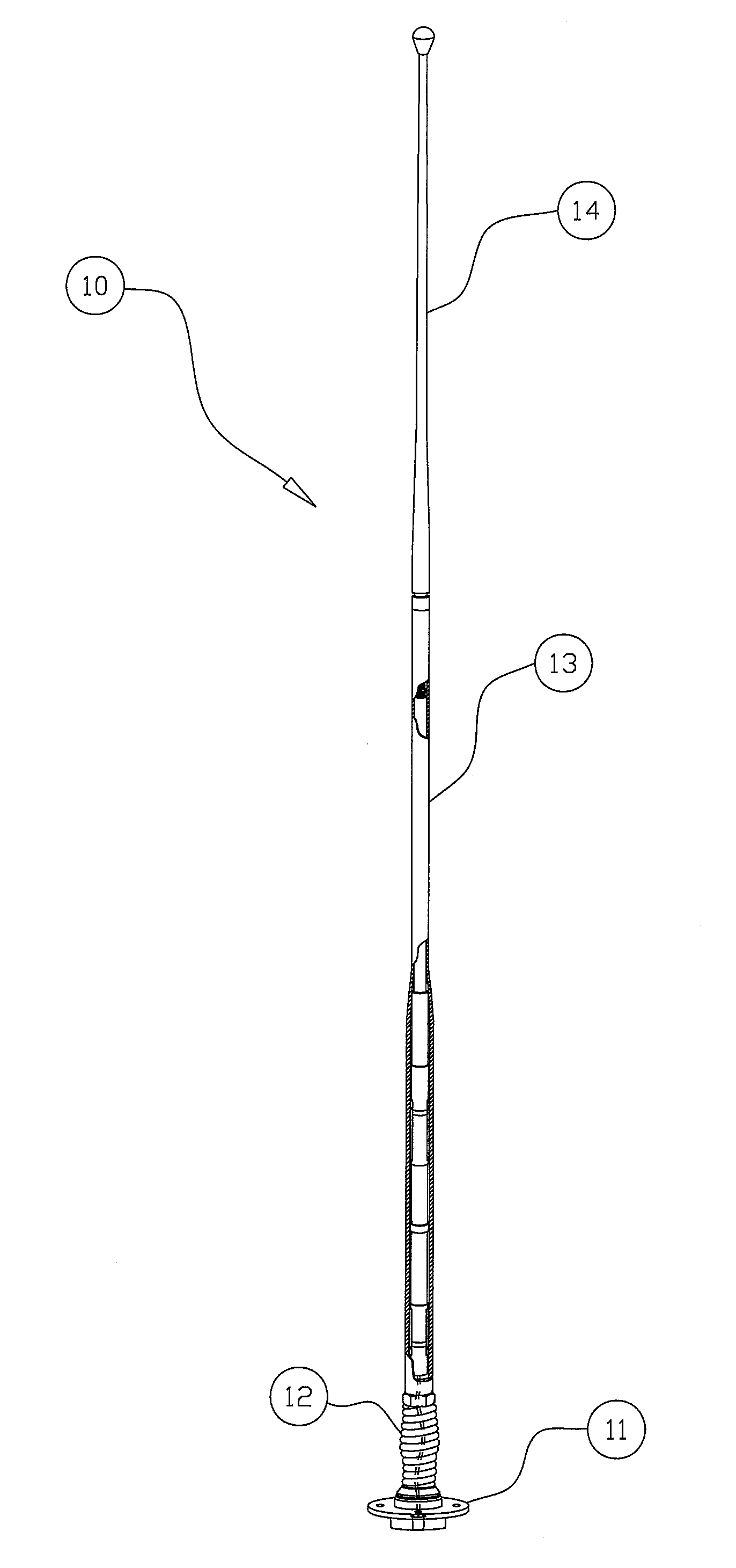
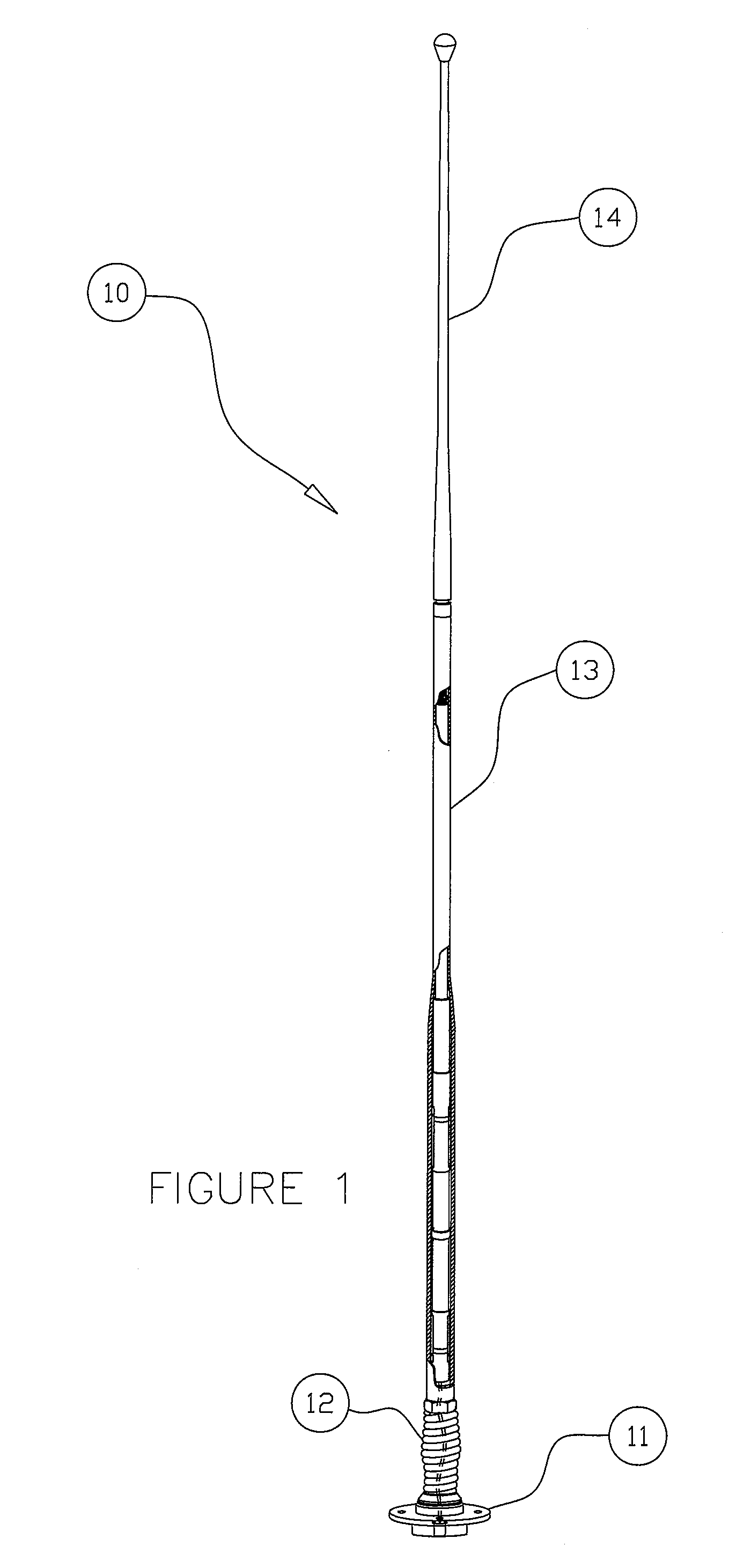
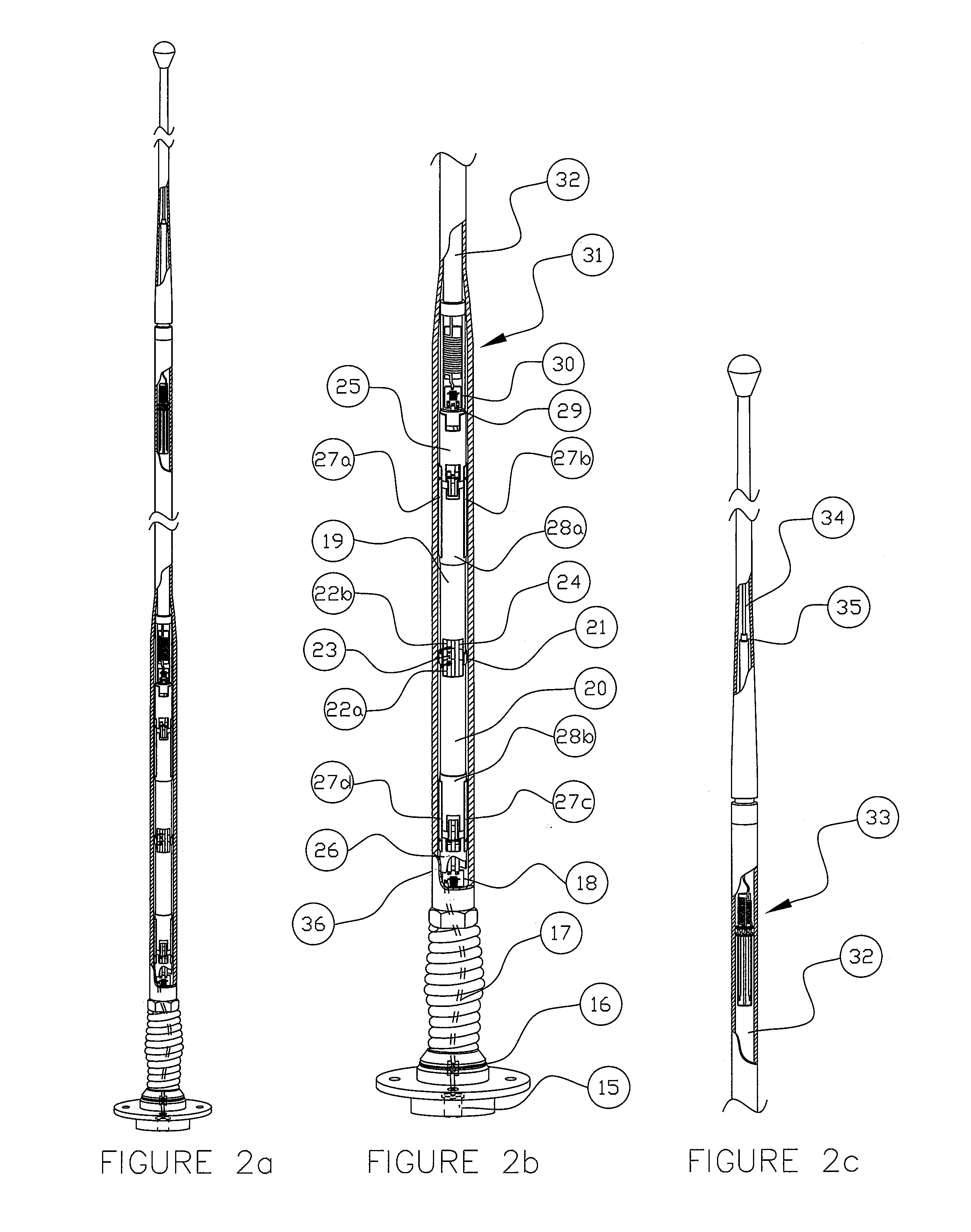
[0031]Referring to FIGS. 1 through 4, the typical multiple band dipole antenna is depicted by the numeral 10. The antenna 10, as a whole, is comprised of a base flange 11, a lower whip section 13 (with integral spring mount) and an upper whip section 14. The base flange 11 is comprised of an aluminum base support, which is mountable to any flat, rigid surface through the use of common hardware, and a large female threaded hole. The integral spring mount, preferably built of a corrosion resisting steel wire is mechanically fastened to the lower whip section 13. The lower whip section 13 contains the UHF dipole and the lower half of the VHF dipole. It has a threaded ferrule at the top to mate to the upper whip section 14. The upper whip section contains the upper half of the VHF dipole. The upper and lower whip sections of the multiple band dipole antenna are enclosed within a rugged, non-conducting envelope 36 preferably of a fibreglass cloth, embedded with an epoxy resin.

[0032]In on...


PUM


Abstract

A vertical dipole-style antenna operable over a wide range of predetermined frequencies that is made up of two collinear dipole antennas fed either in parallel through a single input connector or individually through two input connectors, contained within the same enclosure, where one dipole covers the VHF portion of the band from 30 MHz to 115 MHz and the other dipole covers the remainder of the band from 115 MHz to 512 MHz and together the two dipoles cover the very wide frequency band of 30 to 512 MHz through a single input connector. The VHF dipole is comprised of an existing vehicular dipole antenna design, while the UHF dipole antenna is comprised of radiating elements fed with a specially design coaxial transformer feedline with wide-band capacitive elements coupling the radiating elements to ground, providing variable loading to control the electrical length of the antenna.

Description

FIELD OF INVENTION[0001]The invention relates to broadband antennas used in radio transmission and receiving systems. More particularly, this invention relates to dipole-style antennas having an instantaneous bandwidth between 30 MHz and 512 MHz which exhibits a low voltage standing wave ratio or VSWR of less than 3:1 and provides high transmission gain, while offering independence from proper ground planes. More particularly, this invention describes wideband, vertical dipole antennas of rugged construction so as to survive the harsh environmental conditions commonly found in, although not limited to, vehicular military applications. Furthermore, this invention relates to wideband antennas utilising either a single input or a dual input to create a single antenna capable of covering multiple sub-bands encompassed within the entire frequency range of 30 MHz to 512 MHz.BACKGROUND OF THE INVENTIONS[0002]It is known that broadband antennas have been developed and used for a wide range ...

Claims


Application Information

Patent Timeline
IPC IPC(8): H01Q9/16H01Q21/12H01Q21/00H01Q5/10
CPCH01Q1/1207H01Q21/12H01Q21/10
Inventor PATRICK, POLSKYHAITU, DUONG
Owner VALCOM MFG GRP
Why Eureka
Try Eureka