[0007]The invention features, in one embodiment, marking bones for
surgical procedures (e.g., orthognathic
surgery). A bone marking
system can enable surgeons to copy computer treatment plans to the bone even through a very
small incision, allowing surgeons to perform more sophisticated procedures with less difficulty for the patient and improved outcomes (e.g., faster
recovery times, less pain and discomfort, and less scarring than open procedures). A bone marking
system can be used in both endoscopic and open procedures to transfer treatment plans from computer-based three dimensional
surgical planning tools onto the bone. A system can provide for intraoperative registration of the image to the patient, with no requirement for fiducial markers in the pre-operative images or for a fixation frame attached to the head. The surgeon can mark the bone for ostotomies, screw holes or alignment, and then complete the procedure using instruments without any tracking, using the marks to guide the modification of bone. A bone marking system is less expensive and need not track the motion of multiple surgical instruments as procedures are performed. With operating room costs surpassing $25 per minute, techniques that allow efficient and precise implementation of surgical plans are essential for cost-
effective management of surgical cases.
[0010]The opportunity to minimize incision (and hence
scars) is particularly attractive for maxillofacial surgeons, as virtually everyone is sensitive to the appearance of the face.
Recovery time and patient discomfort can be reduced when less-invasive techniques are employed. Working through smaller incisions limits the visual field from which surgeons use to manipulate instruments, so new methods of locating instruments with respect to the patient's
anatomy are necessary. The bone marking instrument combines minimally invasive therapy with
tissue engineering to eliminate donor site morbidity.
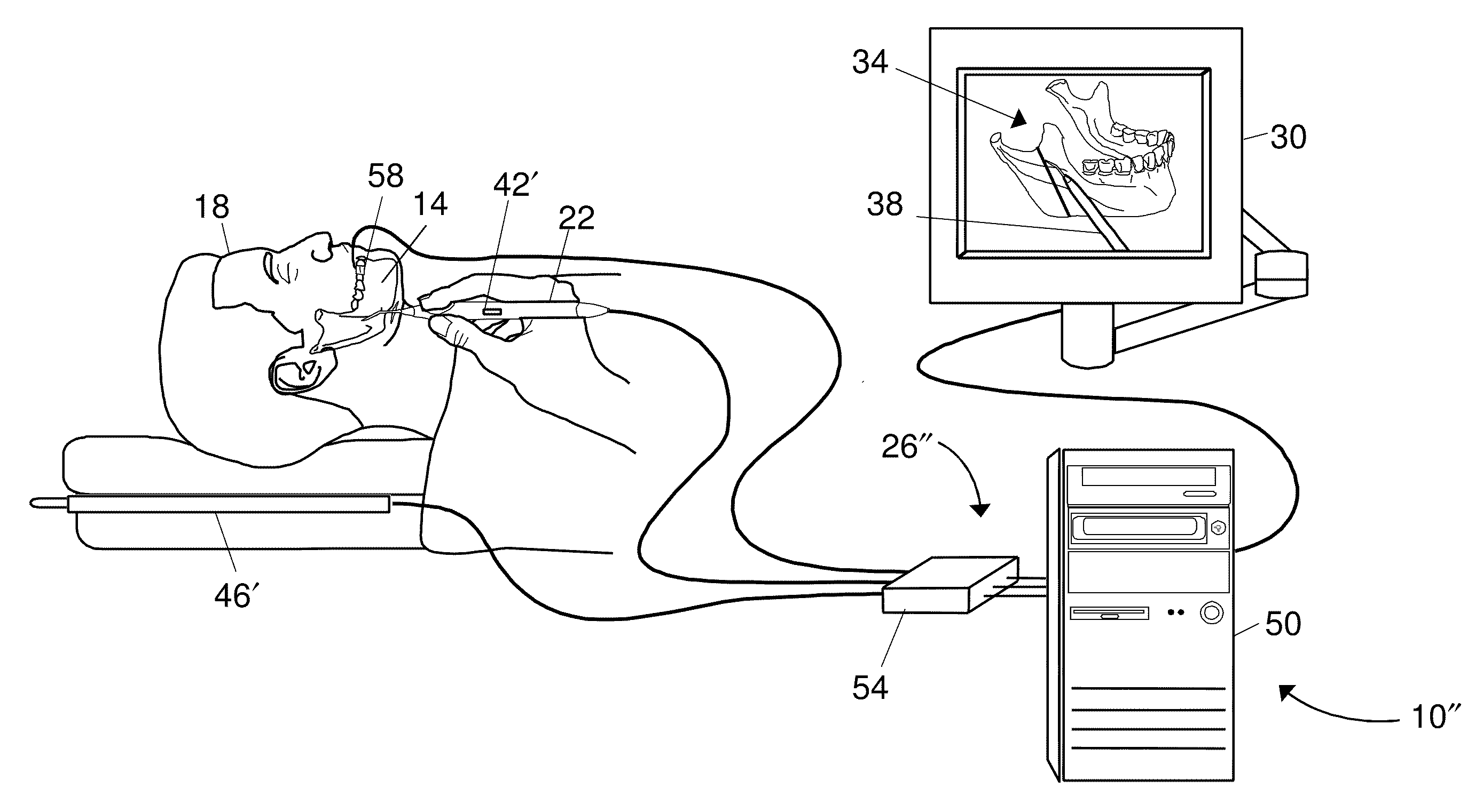
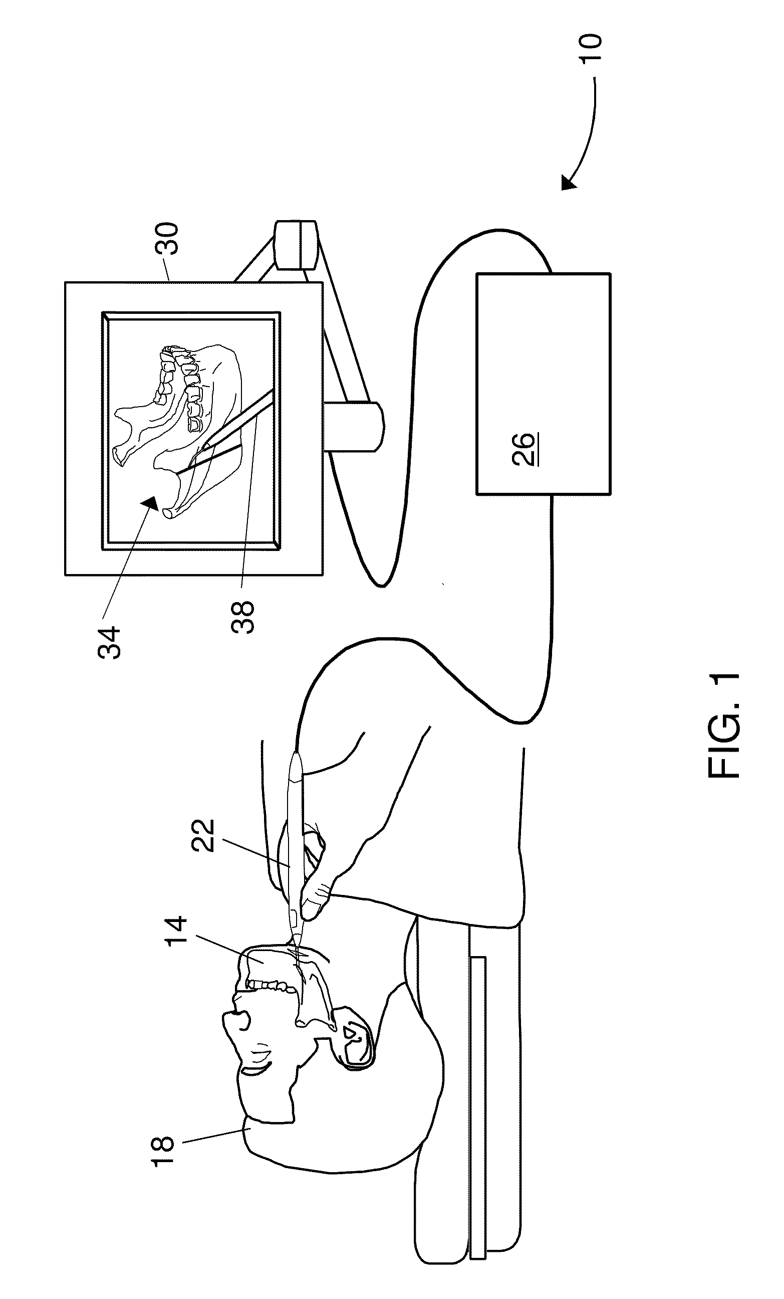
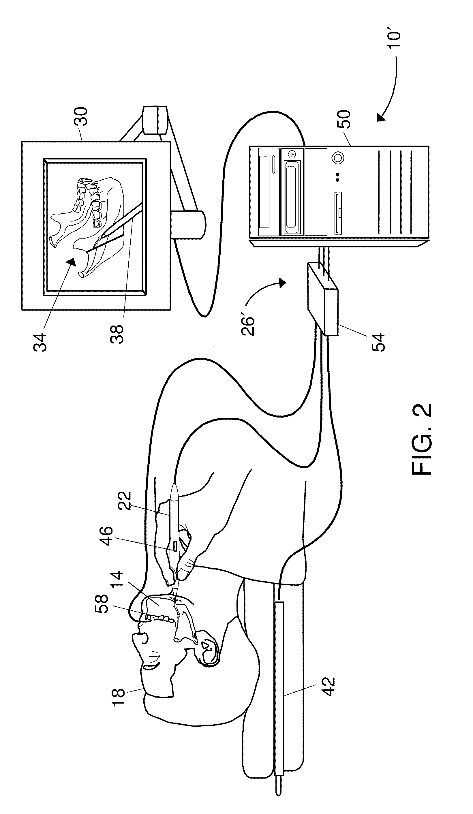
[0011]The bone marking system can assist in the mapping of a
treatment plan from the computer (e.g., a computer-based three-dimensional plan) to the
bone structures to be modified. Because orthognathic surgical reconstruction often involves complex multi-axis manipulations, many surgeons find navigation tools helpful even for open procedures. The bone marking system can also be used as a precision measuring device to, for example, establish symmetry in bilateral procedures. Examples of procedures where the bone marking instrument and method might be used include minimally-invasive (endoscopic) reconstruction and
distraction osteogenesis.
[0014]In yet another aspect, there is an apparatus for marking bone of a patient. The apparatus includes means for imparting pigment to a marking location on the bone of the patient, means for matching at least one
anatomical feature of the bone of the patient to an image of the bone, means for determining a location of the means for imparting pigment relative to the bone, means for showing an image of the location of the means for imparting pigment relative to the image of the bone and facilitating positioning the means for imparting pigment relative to the marking location on the bone.
[0017]In certain embodiments, the tracking system can include and be in separate communication with a
transmitter disposed in a known position relative to the bone of the patient and a
receiver attachable to the marker. The
receiver can sense a
signal from the
transmitter to provide location information of the marker so that the tracking system can determine the location of the marker relative to the bone. In certain embodiments, the tracking system can include and be in separate communication with a
transmitter attachable to the marker and a
receiver disposed in a known position relative to the bone of the patient. The receiver can sense a
signal from the transmitter to provide location information of the marker so that the tracking system can determine the location of the marker relative to the bone.
[0018]The marker can include a transmitter, disposed in a known position relative to the bone of the patient, providing location information from which a tracking system can determine the location of the marker relative to the bone. The marker can include a receiver, disposed in a known position relative to the bone of the patient, sensing a
signal from a transmitter to provide location information of the marker so that a tracking system can determine the location of the marker relative to the bone.

