Thrombectomy and Balloon Angioplasty/Stenting Device

a stenting device and thrombosis technology, applied in the medical field, can solve the problems of affecting the flow of blood through the vessel, the affected blood vessel may close, and the risk of debris being released from the occluded or narrowed area of the blood vessel, and achieves simple thrombosis and less ischemia-time. , the effect of reducing the risk of ischemia

Inactive Publication Date: 2010-12-02
ALASWAD KHALDOON
View PDF16 Cites 20 Cited by
  • Summary
  • Abstract
  • Description
  • Claims
  • Application Information

AI Technical Summary

Benefits of technology

[0019]It is therefore an advantage of the invention to provide a thrombectomy and balloon angioplasty/stenting device wherein the device combines protection, thrombectomy, and therapy in one easy to use device.
[0020]It is another advantage of the invention to provide a thrombectomy and balloon angioplasty/stenting device wherein the device is compatible with the current coronary, bypass, and peripheral vascular intervention usual tools, and there is no need for special guide catheters or guide wires.
[0021]It is yet another advantage of the invention to provide a thrombectomy and balloon angioplasty/stenting device wherein the device protects the main branch and side branches in the native circulation as opposed to distal protection. This protects the entire myocardium at risk for distal embolization. This device is better than the distal protection in the native c

Problems solved by technology

Atherosclerosis involves a buildup of plaque that narrows a blood vessel making it more difficult for blood to flow through the vessel.
Although balloon angioplasty is often successful in enlarging the opening of an obstructed blood vessel, an affected blood vessel may close again.
During balloon angioplasty and/or stenting, there is a risk that debris may be released from the occluded or narrowed area in the blood vessel.
However, this device can be unduly complicated.
Of course, the filte

Method used


Image

  • Thrombectomy and Balloon Angioplasty/Stenting Device
  • Thrombectomy and Balloon Angioplasty/Stenting Device
  • Thrombectomy and Balloon Angioplasty/Stenting Device

Examples


Embodiment Construction

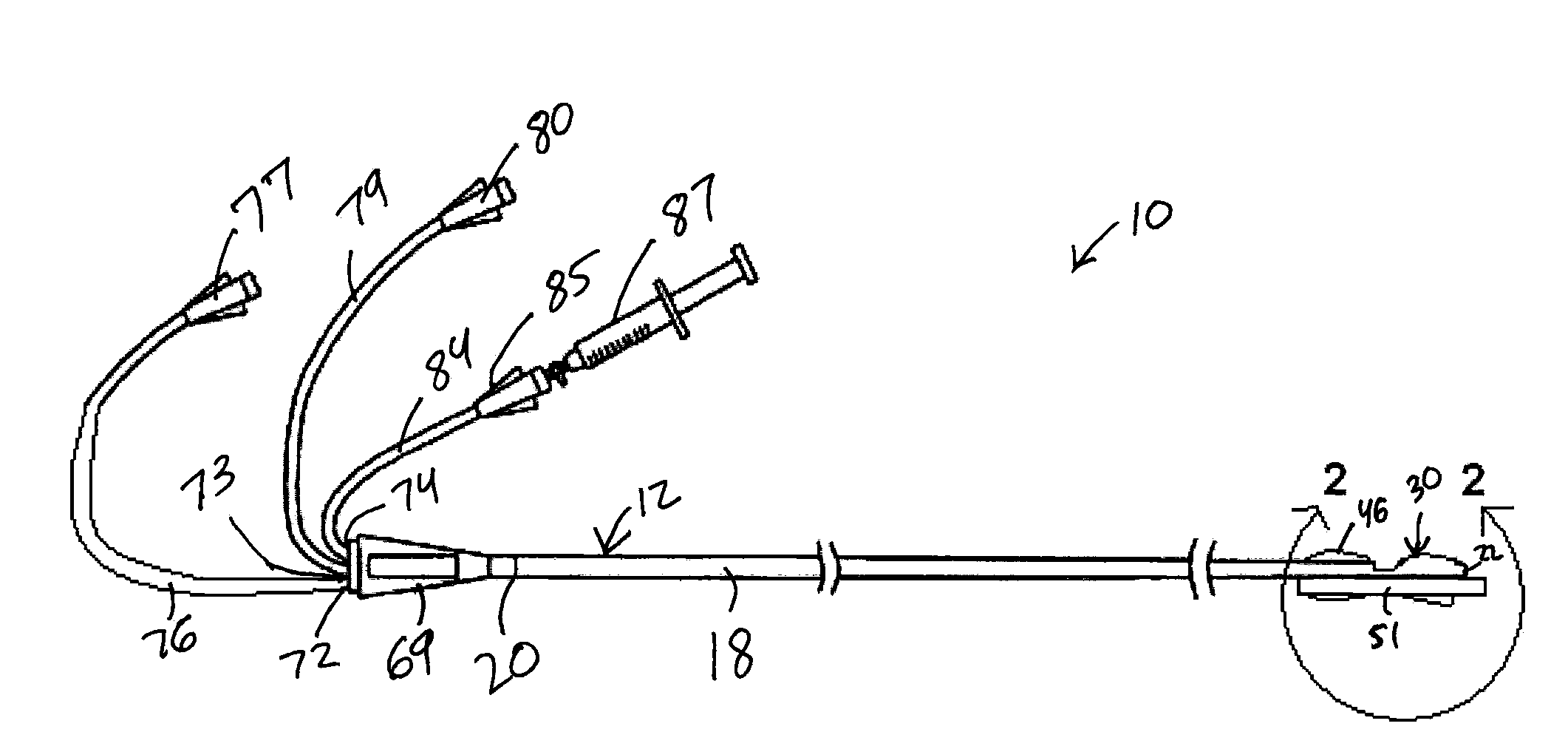
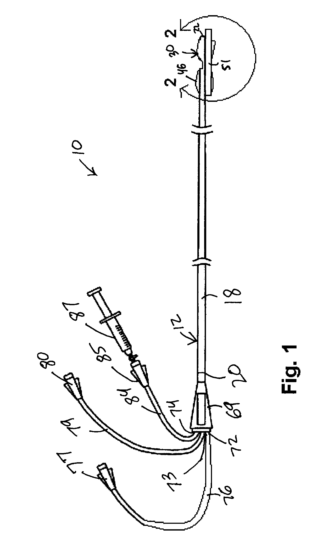
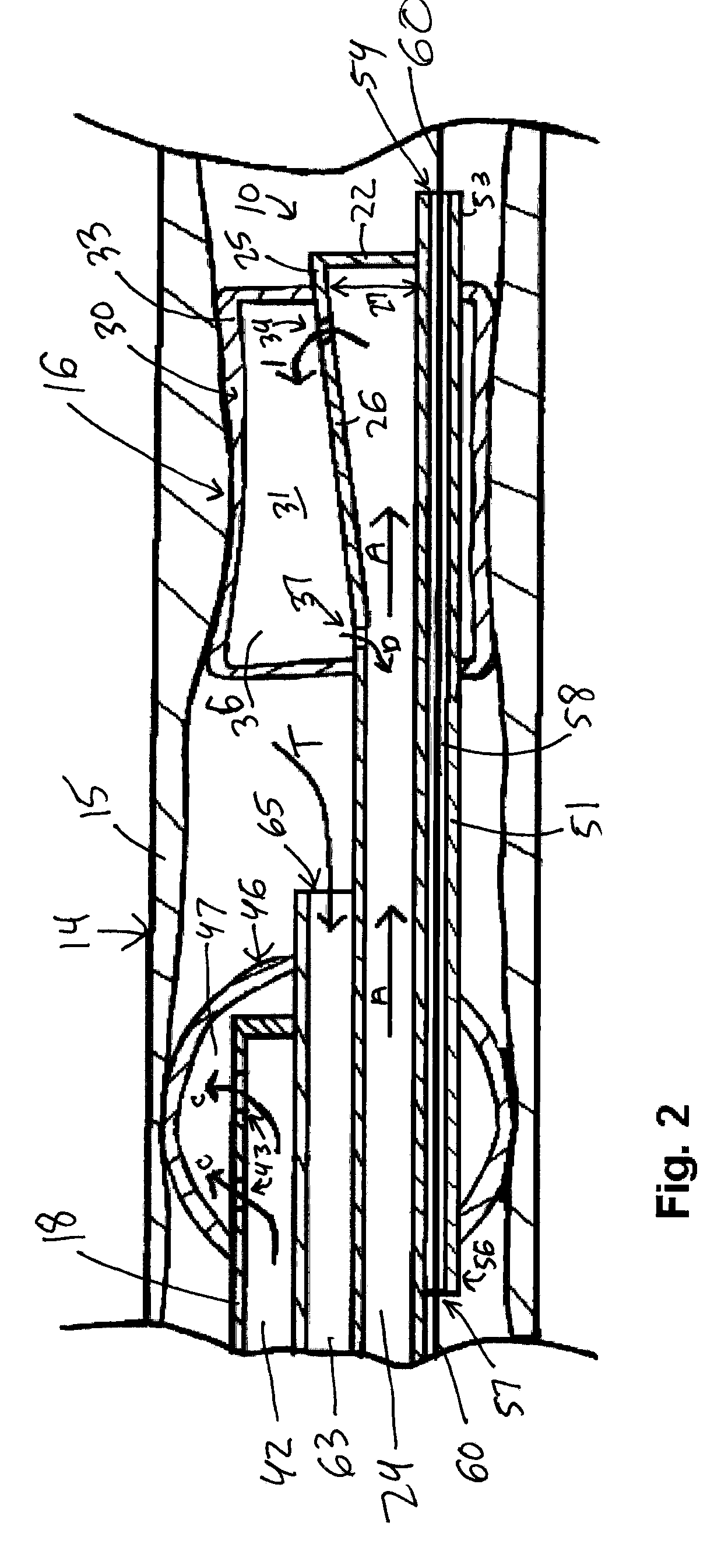
[0035]Looking FIGS. 1 and 2, there is shown one example embodiment of a thrombectomy and balloon angioplasty device 10 according to the invention. The thrombectomy and balloon angioplasty device 10 includes a catheter 12 for insertion in a blood vessel 14 having a wall 15. The wall 15 has a stenosis 16 formed from embolic material. The catheter 12 has a flexible shaft 18 having a proximal end 20 and a distal end 22. The shaft 18 has an angioplasty balloon inflation lumen 24 having a distal end 25. The angioplasty balloon inflation lumen 24 has an outwardly flaring wall 26 that creates a larger angioplasty balloon inflation lumen diameter 27 at the distal end 25 of the angioplasty balloon inflation lumen 24.

[0036]The shaft 18 can be formed from a polyurethane base polymer. Polyurethane can offer advantages over other materials as it is a more durable material enabling the use of thinner lumen walls. It offers less friction for ease of insertion; it is biocompatible; it has good tensi...


PUM


Abstract

A thrombectomy and balloon angioplasty catheter for the removal of blood clots and debris from a blood vessel and/or for the dilation of a narrowed or completely closed segment in the blood vessel is disclosed. The catheter includes a shaft having a proximal end and a distal end, an angioplasty balloon mounted to the shaft adjacent the distal end of the shaft, and an occlusion balloon mounted to the shaft at a location proximally spaced from the angioplasty balloon. A guide wire lumen is arranged on the shaft. The guide wire lumen extends from a first position adjacent the distal end of the shaft to a second position proximal the angioplasty balloon and distal the proximal end of the shaft. The shaft includes an angioplasty balloon inflation lumen in fluid communication with the proximal end of the shaft and an interior space of the angioplasty balloon, an occlusion balloon inflation lumen in fluid communication with the proximal end of the shaft and an interior space of the occlusion balloon, and a thrombectomy lumen in fluid communication with the proximal end of the shaft and a thrombectomy suction port located between the angioplasty balloon and the occlusion balloon.

Description

CROSS-REFERENCES TO RELATED APPLICATIONS[0001]Not Applicable.STATEMENT REGARDING FEDERALLY SPONSORED RESEARCH[0002]Not Applicable.BACKGROUND OF THE INVENTION[0003]1. Field of the Invention[0004]The invention relates to medical devices for the removal of the blood clots and debris from a blood vessel and / or for the dilation of a narrowed or completely closed segment in the blood vessel.[0005]2. Description of the Related Art[0006]Atherosclerosis involves a buildup of plaque that narrows a blood vessel making it more difficult for blood to flow through the vessel. Although atherosclerosis commonly develops in the arteries of the heart, it can strike any blood vessel, such as those feeding the brain, legs, or the kidneys. Atherosclerosis reduces the flow of oxygen-rich blood to these organs.[0007]Balloon angioplasty (also called “percutaneous transluminal angioplasty”—PTA) is a technique performed to increase the size of the opening within the blood vessel by dilating a narrowed or com...

Claims


Application Information

Patent Timeline
IPC IPC(8): A61M25/10A61F2/84
CPCA61F2/958A61M25/003A61M25/0075A61M25/1002A61M25/1011A61M25/104A61M2025/0078A61M2025/0183A61M2025/1052A61B2017/22079A61M25/007A61M25/0026A61M25/09
Inventor ALASWAD, KHALDOON
Owner ALASWAD KHALDOON
Why Eureka
Try Eureka