Method and System for Visual Collision Detection and Estimation

a collision detection and estimation technology, applied in the field of visual collision detection and estimation, can solve the problems of uas flying “nap of the earth” risking collision with ground obstacles, flying at higher altitudes risking collision with other aircraft, and achieving the effect of optimizing the time to collision estimation

Inactive Publication Date: 2010-12-02
BYRNE JEFFREY +1
View PDF6 Cites 164 Cited by
  • Summary
  • Abstract
  • Description
  • Claims
  • Application Information

AI Technical Summary

Benefits of technology

[0018]The present invention is directed to a method and system for visual collision detection and estimation of stationary objects using expansion segmentation. The invention combines visual collision detection to localize significant collision danger regions in forward looking imaging systems (such as aerial video), with optimized time to collision estimation within the collision danger region. The system and method can use expansion segmentation for the labeling of “collision” and “non-collision” nodes in a conditional Markov random field. The minimum energy binary labeling can be determined in an expectation-maximization framework to iteratively estimate labeling using the min-cut of an appropriately constructed affinity graph, and the parameterization of the joint probability distribution for time to collision and appearance. This joint probability can provide global model of the collision region, which can be used to estimate maximum likelihood time to collision over optical flow likelihoods, which can be used to aid with local motion correspondence ambiguity.

Problems solved by technology

For example, UAS's flying “nap of the earth” risk collision with ground obstacles whose position cannot be guaranteed to be known beforehand, such as flight in city canyons and around high-rise buildings as envisioned for future homeland security operations.
UAS's flying at higher altitudes risk collision with other aircraft, that may not include cooperative Traffic Collision Avoidance System (TCAS) deconfliction capability.
The transition of UAS to civilian law enforcement applications has already begun, with police and sheriffs department programs in California, Florida, and Arkansas drawing intense scrutiny from the Federal Aviation Administration and pilots organizations who are concerned that the UAS will pose a hazard to civil and commercial aviation in the National Air Space (NAS).
The primary concern is that UAS lack the ability to sense and avoid (S&A) other aircraft and ground hazards operating in proximity to the UAS, as a manned aircraft would.
Civil and commercial applications for MAVs are not as well developed, although potential applications are extremely broad in scope.
UASs flying nap of the earth risk collision with urban obstacles whose position cannot be guaranteed as known a priori.
Unlike ground vehicles, MAVs introduce aggressive maneuvers which couple full 6-DOF (degrees of freedom) platform motion with sensor measurements, and feature significant SWAP constraints that limit the use of active sensors.
Furthermore, the wingspan limitations of MAVs limit the range resolution of stereo configurations, therefore an appropriate sensor for collision detection on a MAV is monocular vision.
While monocular collision detection has been demonstrated in controlled flight environments, it remains a challenging problem due to the low false alarm rate needed for practical deployment and the high detection rate requirements for safety.
Structure from motion (SFM) is the problem of recovering the motion of the camera and the structure of the scene from images generated by a moving camera.
However, SFM techniques consider motion along the camera's optical axis as found in a collision scenario to be degenerate due to the small baseline, which results in significant triangulation uncertainty near the focus of expansion which must be modeled appropriately for usable measurements.
This approach has been widely used in environments that exhibit a dominant ground plane, such as in the highway or indoor ground vehicle community, however the ground plane assumption is not relevant for aerial vehicles.
These strong assumptions limit the operational envelope, which have lead some researchers to consider the qualitative properties of the motion field rather than metric properties from full 3D reconstruction as sufficient for collision detection.
However, this does not provide a measurement of time to collision and does not localize collision obstacles in the field of view.
This model has been implemented on ground robots for experimental validation, however the biophysical LGMD neural network model has been criticized for lack of experimental validation, and robotic experiments have shown results that do not currently live up to the robustness of insect vision, requiring significant parameter optimization and additional flow aggregation schemes for false alarm reduction.
While insect inspired vision is promising, experimental validation in ground robotics has shown that there are missing pieces.

Method used


Image

  • Method and System for Visual Collision Detection and Estimation
  • Method and System for Visual Collision Detection and Estimation
  • Method and System for Visual Collision Detection and Estimation

Examples


Embodiment Construction

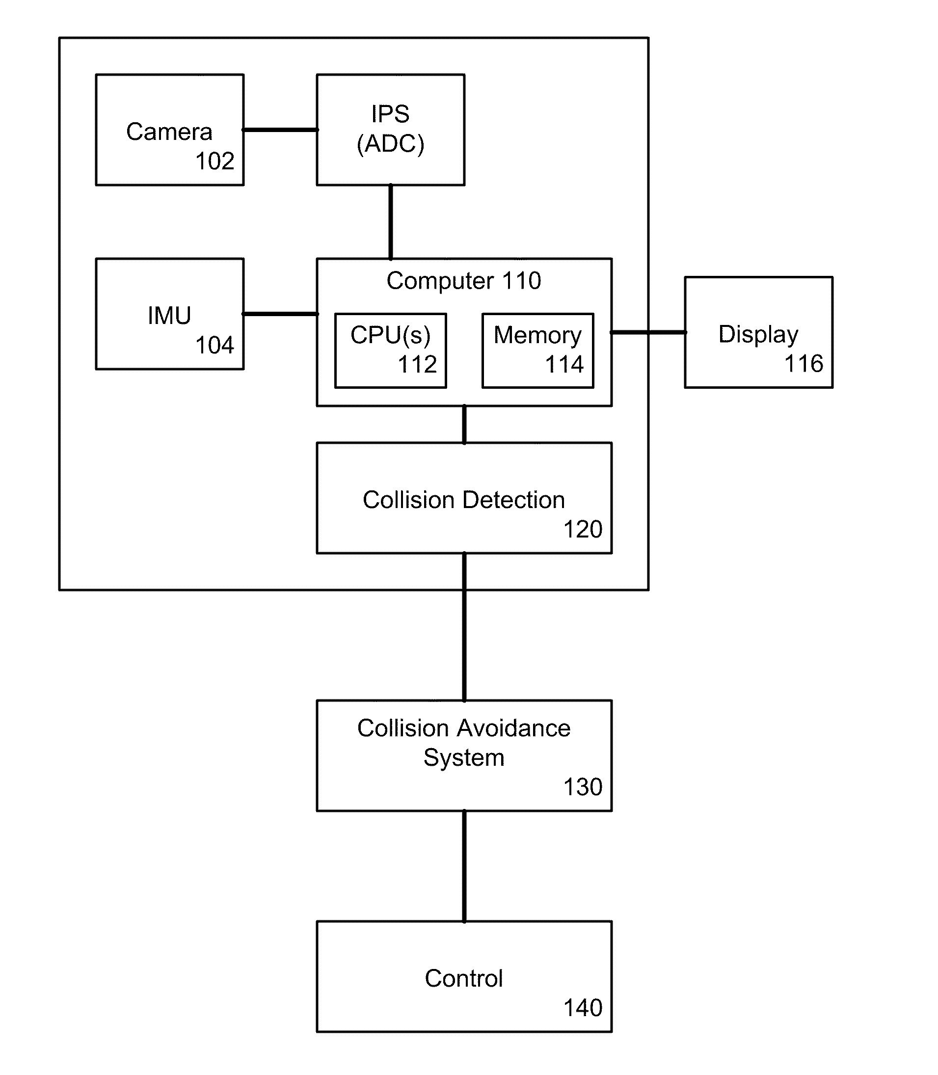
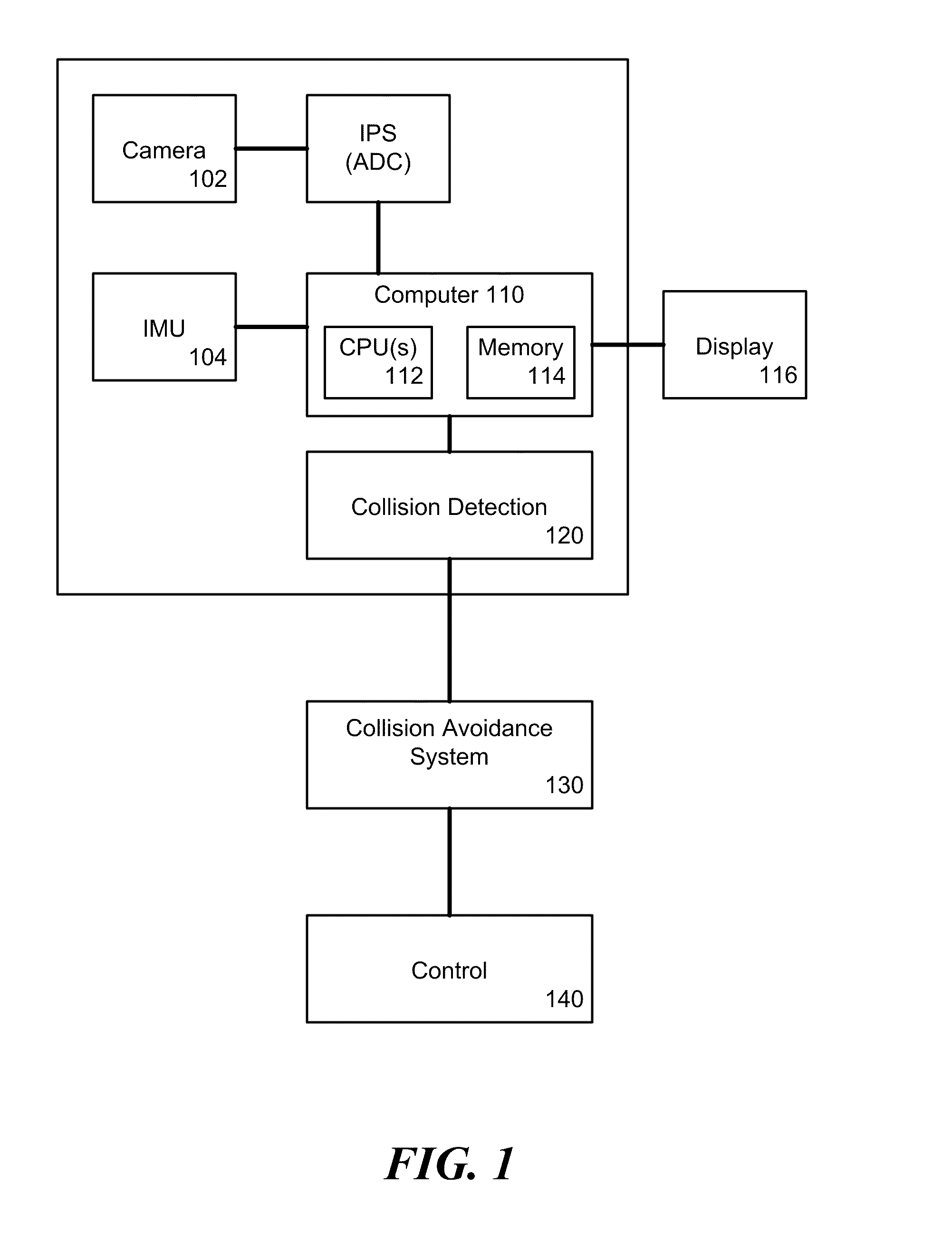
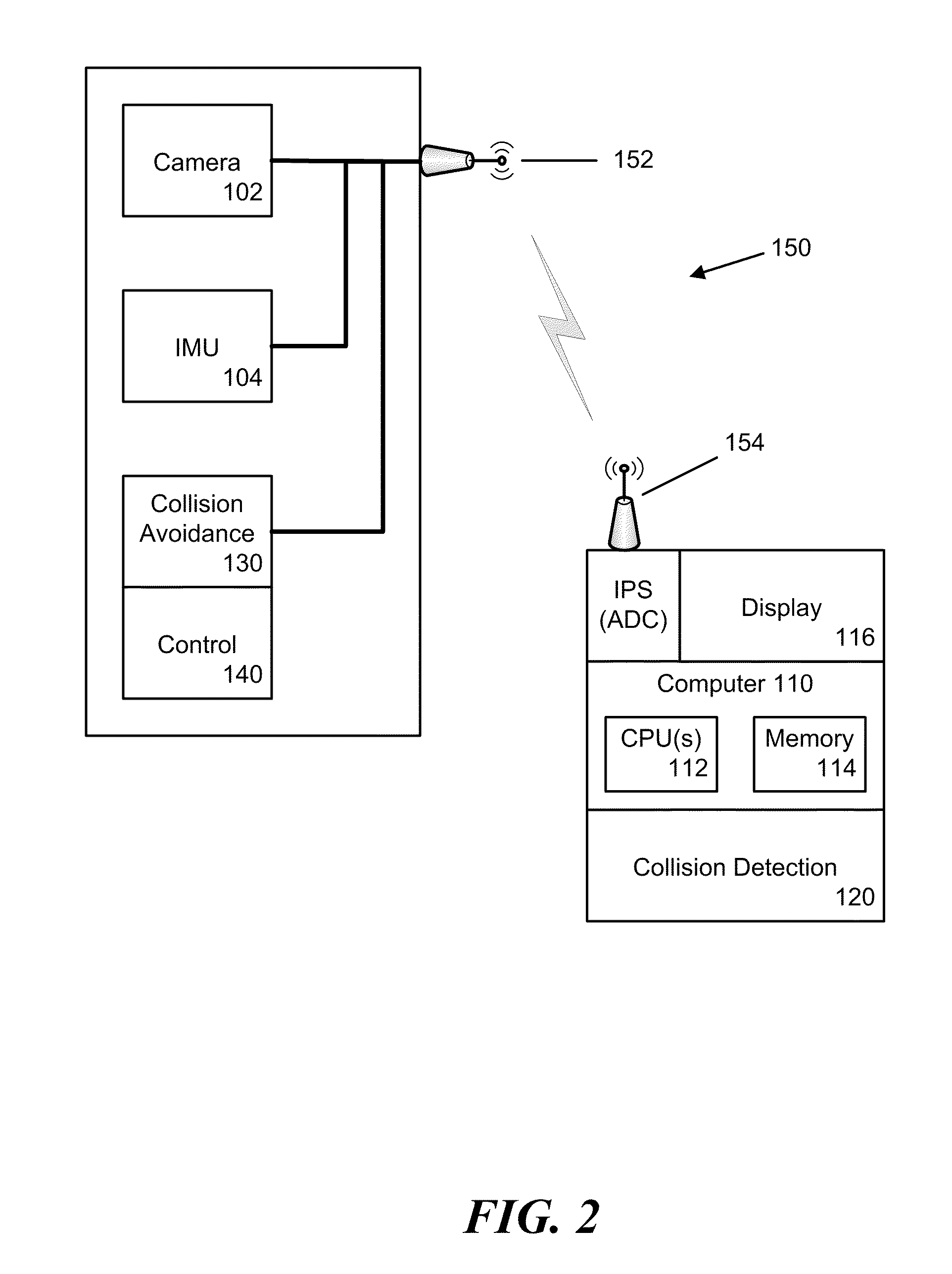
[0033]The present invention is directed to a method and system for collision detection and estimation. In accordance with one embodiment of the invention, system (in accordance with the method of the invention), using images and inertial aiding, formulates a detection of collision dangers, an estimate of time to collision for detected collision dangers, and provides an uncertainty analysis for this estimate.

[0034]In accordance with the invention, a moving vehicle, such as a UAS, MAV, a surface vehicle traveling on the ground or water uses images generated by an image source, such as a still or video camera to detect stationary objects in the path of motion of the vehicle and determine an estimate of the time to collision, should the vehicle remain on the present path. The collision detection and estimation system uses inertial information from an inertial information source, such as an inertial measurement unit (IMU) to determine constraints on corresponding pixels between a first a...


PUM


Abstract

Collision detection and estimation from a monocular visual sensor is an important enabling technology for safe navigation of small or micro air vehicles in near earth flight. In this paper, we introduce a new approach called expansion segmentation, which simultaneously detects “collision danger regions” of significant positive divergence in inertial aided video, and estimates maximum likelihood time to collision (TTC) in a correspondenceless framework within the danger regions. This approach was motivated from a literature review which showed that existing approaches make strong assumptions about scene structure or camera motion, or pose collision detection without determining obstacle boundaries, both of which limit the operational envelope of a deployable system. Expansion segmentation is based on a new formulation of 6-DOF inertial aided TTC estimation, and a new derivation of a first order TTC uncertainty model due to subpixel quantization error and epipolar geometry uncertainty. Proof of concept results are shown in a custom designed urban flight simulator and on operational flight data from a small air vehicle.

Description

CROSS-REFERENCE TO RELATED APPLICATIONS[0001]This application claims any and all benefits as provided by law of U.S. Provisional Application No. 61 / 176,588 filed 8 May 2009 which is hereby incorporated by reference in their entirety.STATEMENT REGARDING FEDERALLY SPONSORED RESEARCH[0002]This invention was made with Government support under contract (FA8651-07-C-0094) awarded by the US Air Force (AFRL / MNGI). The US Government has certain rights in the invention.REFERENCE TO MICROFICHE APPENDIX[0003]Not ApplicableBACKGROUND[0004]1. Technical Field of the Invention[0005]The present invention is directed to a method and system for collision detection and estimation using a monocular visual sensor to provide improved safe navigation of remotely controlled vehicles, such small or micro air vehicles in near earth flight and ground vehicles around stationary objects.[0006]2. Description of the Prior Art[0007]The use of Unmanned Aircraft Systems (UAS) for reconnaissance, surveillance, and tar...

Claims


Application Information

Patent Timeline
Patent Type & Authority Applications(United States)
IPC IPC(8): G08G1/16G06K9/00
CPCG06T2207/30248G06T7/73
Inventor BYRNE, JEFFREYMEHRA, RAMAN K.
Owner BYRNE JEFFREY
Why Eureka
Try Eureka