Vacuum cleaner head

a vacuum cleaner and vacuum head technology, applied in the field of vacuum cleaners, can solve the problems of paper bag contamination, dust and debris being lifted and stored,

Inactive Publication Date: 2010-12-09
C ART
View PDF2 Cites 14 Cited by
  • Summary
  • Abstract
  • Description
  • Claims
  • Application Information

AI Technical Summary

Benefits of technology

[0004]It is an object of the present invention to overcome or substantially ameliorate at least

Problems solved by technology

Another problem associated with vacuum cleaners is that the dust and debris lifted and stored in a receptacle s

Method used


Image

  • Vacuum cleaner head
  • Vacuum cleaner head
  • Vacuum cleaner head

Examples


Embodiment Construction

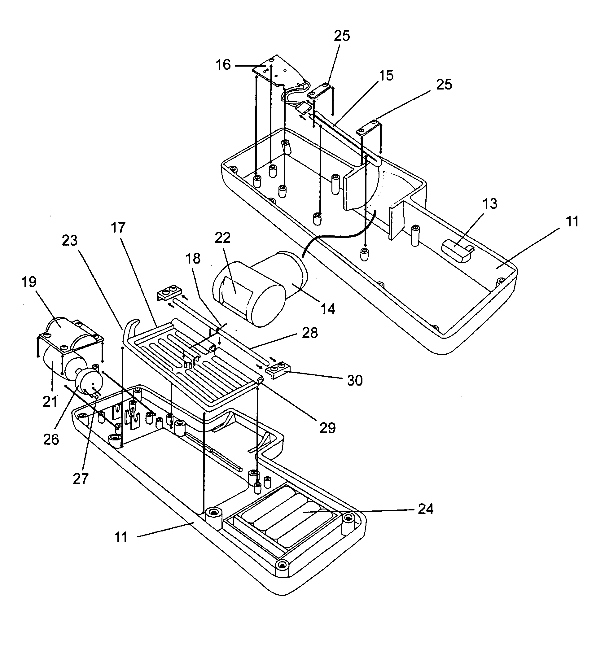
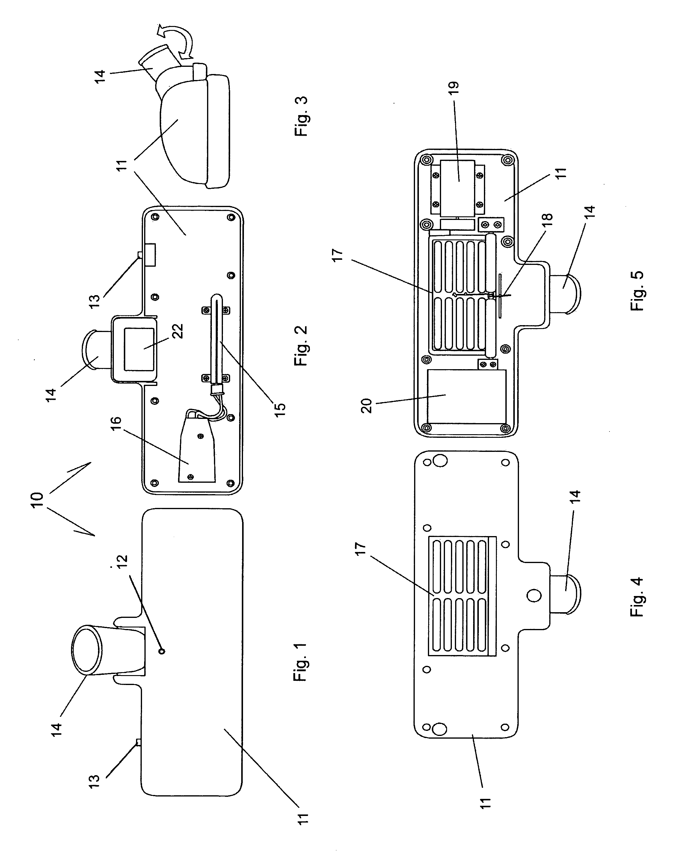
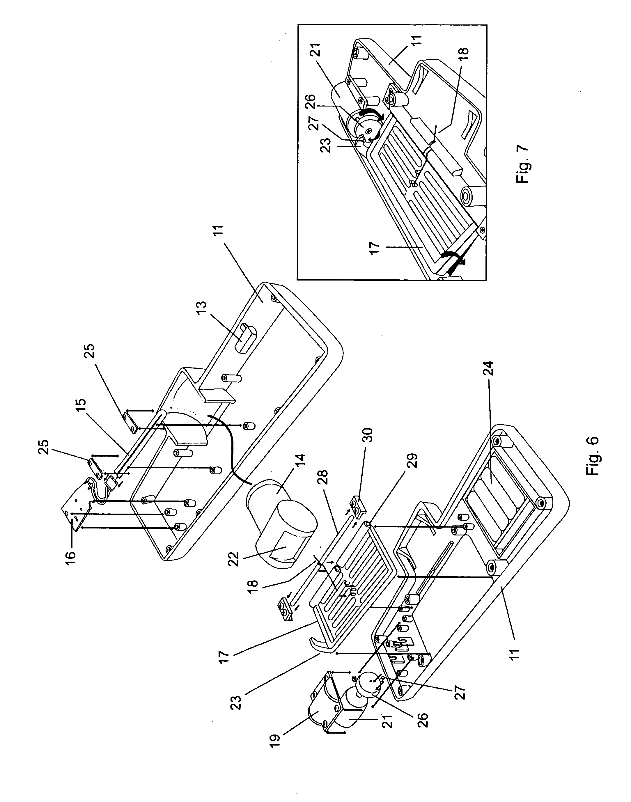
[0026]In the accompanying drawings there is depicted schematically a vacuum cleaner head 10 comprising a body 11 typically formed as a thermoplastics moulding. The body has pivotally extending from it a vacuum hose or pole attachment 14 via which air is drawn through the body en route to a vacuum cleaner.

[0027]Inside the body there is provided a PCB 16 having wires extending to an ultraviolet fluorescence lamp 15.

[0028]A covered battery compartment 20 houses a number of batteries 24. A switch 13 conveys power from the batteries 24 to the PCB 16. A power indicator LED 12 is provided upon the body 11 to indicate that the switch 13 is in the ON position.

[0029]Pivotally attached to the underside of the body 11 is a perforated agitation plate 17. The agitation plate 17 includes a hinge 29 through which a hinge pin 28 extends. A pair of hinge clamps 30 secures the hinge pin 28 to the body 11. Integrally moulded with the agitation plate 17 is a cam follower 23.

[0030]An electric motor 21 is...


PUM


Abstract

A vacuum cleaner head for attachment to a suction pipe or hose of a vacuum cleaner includes a body, an inlet through which air from a surface enters the body en route to the vacuum cleaner, and an agitation plate attached movably to the body across or adjacent to the inlet and adapted to beat against the surface in use. An ultraviolet lamp illuminates and disinfects dust and debris as is passes through the head.

Description

BACKGROUND OF THE INVENTION[0001]The present invention relates to vacuum cleaners. The invention more particularly, although not exclusively, relates to a vacuum cleaner head having a carpet or fabric beating feature to raise dust from carpet pile or fabrics such as bed linen and curtains.[0002]Vacuum cleaner heads for attachment to suction poles of vacuum cleaners usually comprise a simple brush or carpet slider or rollers to engage a hard floor or carpet surface as the case may be. These heads rely almost solely on the suction provided by the vacuum cleaner to lift dust and debris from the surface. Some vacuum cleaner heads known as “turbo heads” have a rotating drum with peripheral bristles. These rely on energy in the airflow to cause rotation of the drum and bristles and therefore some of the energy of the airflow which might otherwise be useful for lifting dust and debris is exploited.[0003]Another problem associated with vacuum cleaners is that the dust and debris lifted and ...

Claims


Application Information

Patent Timeline
IPC IPC(8): A47L9/04
CPCA47L9/02A47L9/0411A47L9/0483
Inventor CHAN, MAN-YAN
Owner C ART
Why Eureka
Try Eureka