Electric Rotating Tool

a technology of rotating tools and electric motors, which is applied in the direction of portable power-driven tools, manufacturing tools, instruments, etc., can solve the problems of rapid increase in electric motor temperature, thermal damage, and burnout of an insulating layer of electric motors, so as to prevent burnout of motors and inverter circuit parts (motor drive circuit parts) and improve the operating efficiency per one time of charge of battery packs. , the effect of accurate and appropriate detection

Active Publication Date: 2010-12-09
HITACHI KOKI CO LTD
View PDF14 Cites 93 Cited by
  • Summary
  • Abstract
  • Description
  • Claims
  • Application Information

AI Technical Summary

Benefits of technology

[0058]According to a characteristic of the above described present invention, the first threshold value (Ir) and the second threshold value (Nr) are set in accordance with the magnitude of the PWM duty of the PWM signal; therefore, even in an operation in which the PWM duty is small and rotation torque is small, the locked state of the motor can be accurately and appropriately detected in accordance with load torque. In other words, the locked state can be appropriately detected in accordance with the magnitude of the load of the motor. As a result, burnout of the motor and the inverter circuit part (motor drive circuit part) can be prevented. In addition, since detection of the locked state in accordance with the load state can be carried out, the operating efficiency per one time of charge of the battery pack can be improved.
[0059]According to another charact...

Problems solved by technology

However, in the driver drill used in the drill mode, when the load in the cutting operation becomes equal to or larger than allowable torque of the electric motor, the electric motor is caused to be in a locked state, large current flows therein, and the temperature of ...

Method used


Image

  • Electric Rotating Tool
  • Electric Rotating Tool
  • Electric Rotating Tool

Examples


first embodiment

[0080]Hereinafter, an embodiment of the present invention will be explained in detail based on drawings. Note that, in all the drawings for explaining present embodiments, the members having the same functions are denoted by the same reference numerals, and repetitive explanations will be omitted.

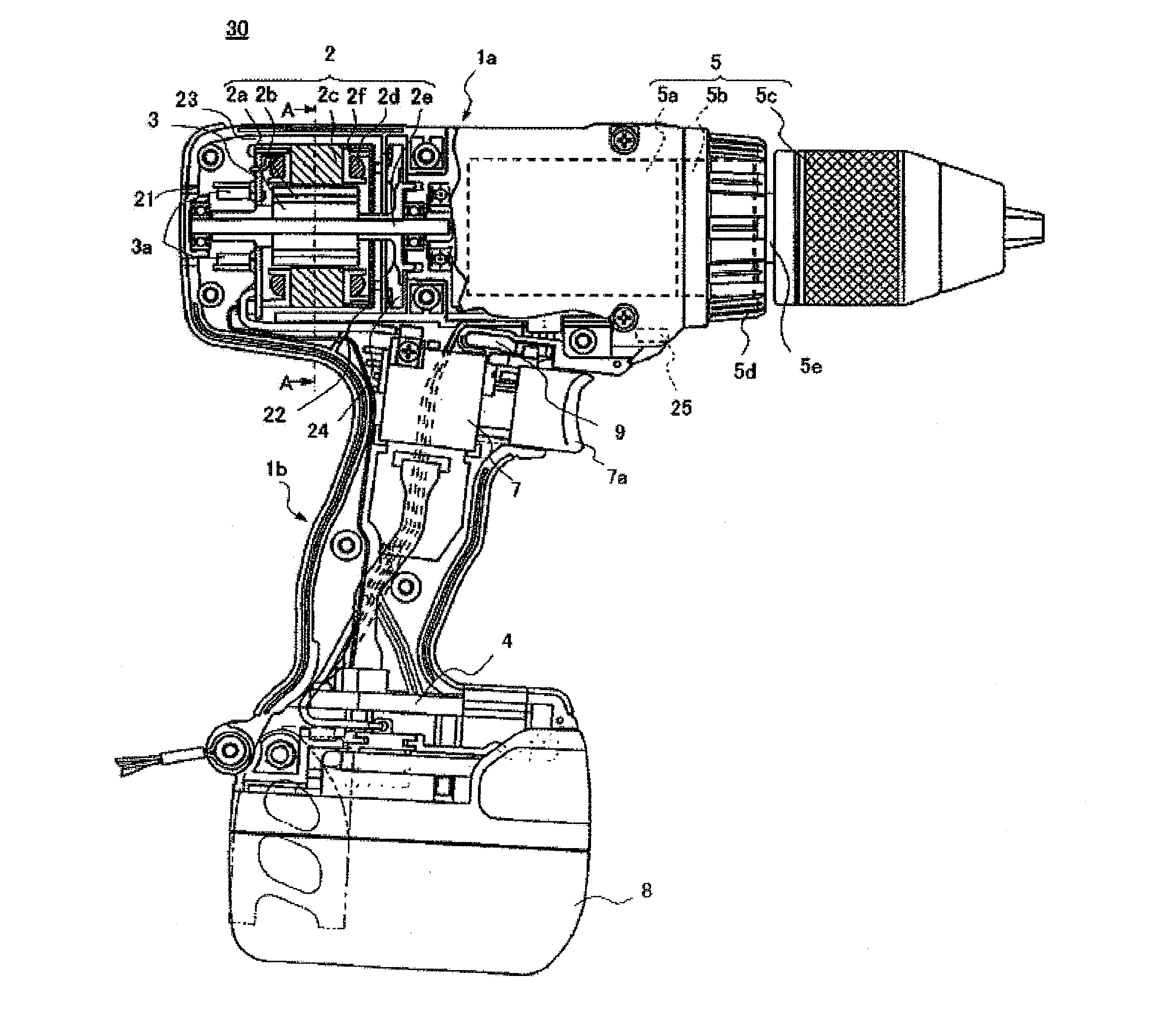
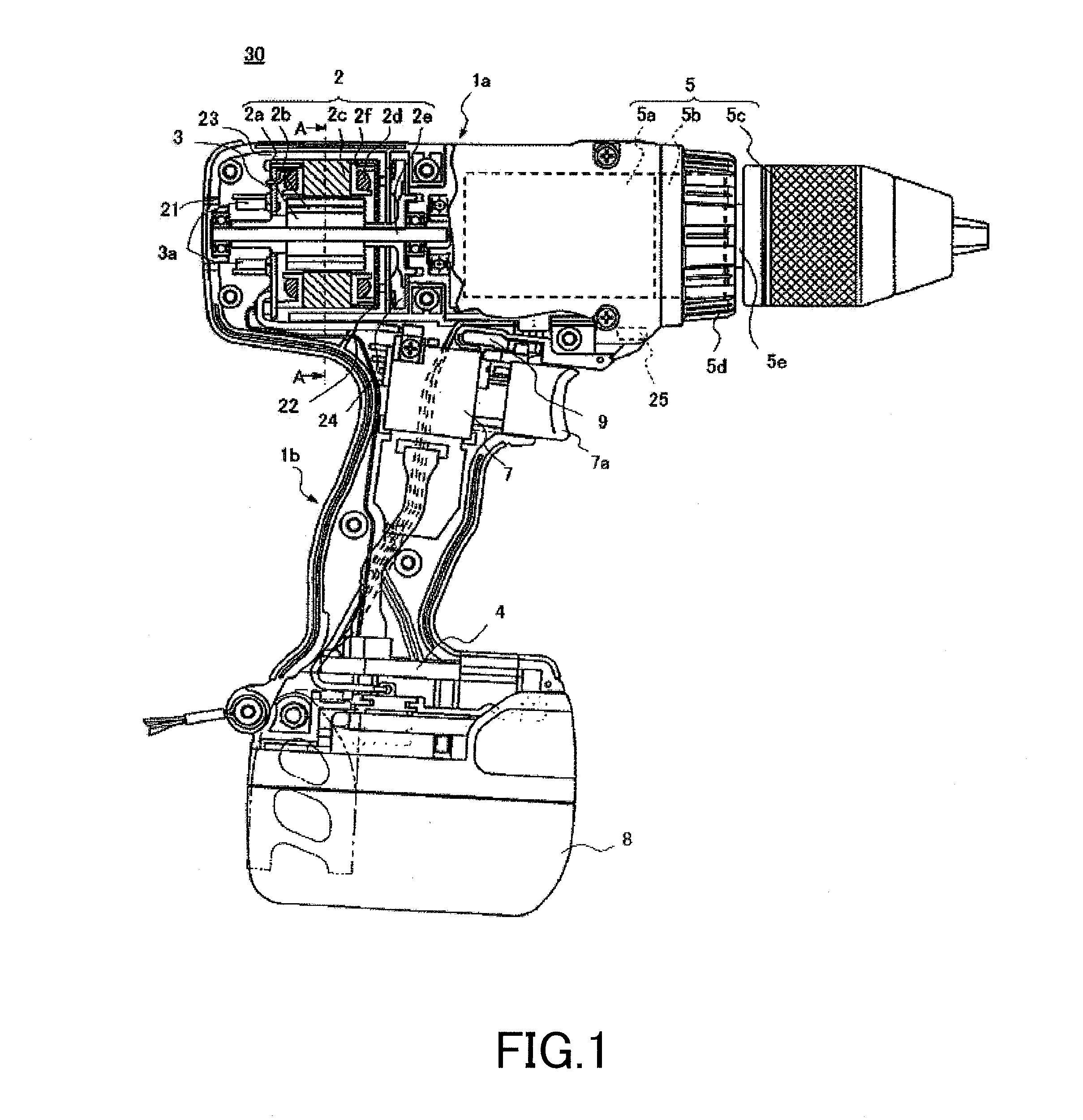
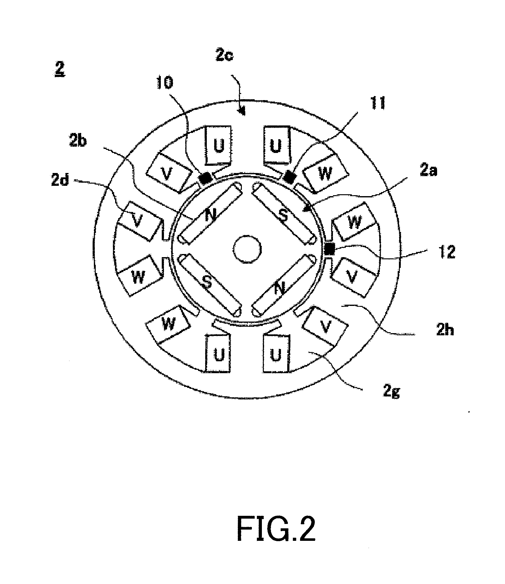
[0081]FIG. 1 is an overall structure drawing of a cordless-type driver drill according to an embodiment of the present invention. FIG. 2 is a partial cross-sectional drawing of the driver drill (brushless DC motor) along a line A-A shown in FIG. 1. Furthermore, FIG. 3 is a functional block diagram showing the entirety of the driver drill shown in FIG. 1.

[0082][Assembly Configuration of Electric Rotating Tool]

[0083]As shown in FIG. 1, a motor 2 is housed in a body housing part 1a of the driver drill 30. A tip tool such as a driver or a drill (not shown) is connected to the motor 2 via a power transmission part 5. The power transmission part 5 transmits the driving force of the motor 2 to the...

second embodiment

[0140]Next, a second embodiment of the present invention will be explained.

[0141]FIG. 8 is a control flow chart in which the control circuit part 4 of the driver drill detects the locked state of the motor 2 in order to protect the motor 2 from an overcurrent. Note that, in the determination or processing steps (steps) of the control flow chart shown in FIG. 8, the steps same as the determination or processing steps of the control flow chart according to the above described first embodiment shown in FIG. 6 are denoted by the same reference numerals, and detailed explanations of the steps are omitted.

[0142]The computing part 20 of the control circuit part 4 according to the present embodiment detects, as the lock detection means, that the motor 2 has become the locked state and then further functions as a motor stopping means, which stops drive of the motor 2.

[0143]As shown in FIG. 8, the lock detection flow chart from the activation process (step 400) of the motor 2 to the lock dete...

third embodiment

[0152]Next, a third embodiment of the present invention will be explained.

[0153]FIG. 12 shows a control flow executed by the control circuit part 4 of the driver drill 30 according to the present embodiment. In the present embodiment, the control circuit part 4 detects the locked state of the motor 2 and protects the motor 2 of the locked state from an overcurrent. Note that, in determination or processing steps of the control flow according to the present embodiment shown in FIG. 12, the steps same as the determination or processing steps of the control flows according to the above described first and second embodiments are denoted by the same reference numerals, and detailed explanations of the steps are omitted.

[0154]In the above described second embodiment, in step 424, the lock allowable time Tstop is uniquely determined based on the magnitude of the motor current, i.e., the magnitude of the threshold value Ir only. However, in the present embodiment, the ambient temperature of...


PUM


Abstract

A current detection circuit (18) detects that a drive current of the stator coil (2d) is exceeding a threshold value Ir. A rotation number detection circuit (17) detects that the number of rotations of a rotor (2a) is lower than a threshold value Nr. A computing part (20) outputs a PWM signal which switches a semiconductor switching element (3a) of the inverter circuit part (3). The computing part (20) changes the threshold values Ir and Nr in accordance with the PWM duty of the PWM signal determined in accordance with a pressed distance of a switch trigger (7) and detects a locked state of the motor (2) on the conditions that the motor current I is exceeding the set threshold value Ir and that the number of rotations N thereof is lower than the threshold value Nr.

Description

TECHNICAL FIELD [0001]The present invention relates to an electric rotating tool, a control method, and a program and, in particular, to an electric rotating tool, a control method, and a program having a lock detection function of detecting a locked state of a motor, for example, a brushless DC motor, that is used as a drive source.BACKGROUND ART [0002]Conventionally, in a tightening operation of a fastener such as a bolt, nut, or screw, an electric rotating tool such as an impact driver or a driver drill is used. In the impact driver, an electric motor is provided, and a power transmission shaft which decelerates and, at the same time, transmits the rotating force of the electric motor is provided. Furthermore, an impact mechanism including a hammer is provided on the power transmission shaft. The power transmission shaft is coupled with an anvil via the impact mechanism. When an operation that the hammer and the anvil are engaged with each other in a striking manner is repeated, ...

Claims


Application Information

Patent Timeline
IPC IPC(8): B25F5/00B25B21/00H02P29/02
CPCB25F5/00H02P29/021H02H7/0854H02P29/0241B25B23/1475
Inventor IWATA, KAZUTAKAYOSHIDA, KENICHIROUWATANABE, SHINJI
Owner HITACHI KOKI CO LTD
Why Eureka
Try Eureka